LG-25-7N-ATV Owner’s Manual
OWNER’S MANUAL
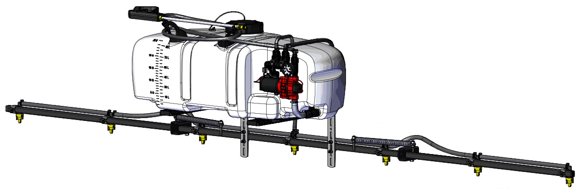
Model: LG-25-7N-ATV (5302951)
(25 Gallon Lawn & Garden/ATV Sprayer)

Caution: When fully filled with water, this sprayer will weigh 275 lbs.. Consult the owner’s manual for your vehicle to verify that you are within it’s load-carrying capacity.
Technical Specifications
- 25 Gal. Corrosion-Resistant Polyethylene Tank
- 12 Volt Diaphragm Pump, 2.4 GPM-60 PSI
- 20 Ft. Handgun Hose (3/8″ I.D.)
- 25 Ft. Vertical throw, 40 Ft. Horizontal Throw
- 7-Nozzle Boom Assembly (140″ Spray Coverage)
- Fold-Away Outer Boom Members
- Corrosion-Resistant Nylon Nozzles
- Check Valve Strainers, 50 Mesh, 5 PSI
General Information
Thank you for purchasing this product. The purpose of this manual is to assist you in operating and maintaining your lawn & garden ATV sprayer.


BEFORE RETURNING THIS PRODUCT FOR ANY REASON, PLEASE CALL
1-800-831-0027
MONDAY-FRIDAY, 8:00 AM TO 5:00 PM CST
If you should have a question or experience a problem with your Fimco Industries Product: Visit our website @ www.fimcoindustries.com or call the Toll free number above. Our technical support representatives will be happy to help you. In most cases a customer service rep. can resolve the problem over the phone.
To obtain prompt, efficient service, always remember to give the following information….
- Correct Part Description and/or part number
- Model number and Serial Number
Part descriptions and numbers can be obtained from the illustrated parts list section(s) of this manual.
Retain a copy of your receipt for your unit, as it will be required to validate any warranty service. Warranted against manufacturer or workmanship defects from date of purchase with copy of receipt: Homeowner Usage: Sprayer-One Year and Pump-Two Years.
Commercial Usage: Sprayer and Pump-90 Days.

Assembly Instructions
- Make sure the contents of the sprayer’s carton match the items shown on page 2 of the manual.
- Follow the steps on pages 3, 4 & 5 to properly assemble the sprayer.
- After assembly is complete and before testing your sprayer, make sure you connect the electrical hook-up to the end of your pump and clip the clips to a fully charged battery.
***IMPORTANT REMINDER***

This sprayer comes with an On/Off (shut-off) valve located at the inlet location of the tank, towards the underside. (See Detail A). You must make sure the valve is in the `open’ position before using your sprayer.

1000 FIMCO Lane, P.O. Box 1700, North Sioux City, SD 57049 Toll Free Phone: 800-831-0027 : Toll Free Fax: 800-494-0440
[5195131
(01/20)]
Contents of your sprayer’s carton (LG-25-7N-ATV – 5302951):


7-Nozzle Boom (5277780), 7-Nozzle Harness (5277696) & Bag of 7 Nozzle Clamps (5277730)
Contents of Parts Bag #5281080

| Ref. # | Part # | Description | Qty |
| 1 | 5278114 | Lead Wire Assembly w/15 Amp Fuse (96″ Long) | 1 |
| 1. | 5157238 | 15 Amp Regular Blade Fuse | 1 |
| 2 | 5167097 | 2″ Dry 100# Back Mount Gauge | 1 |
| 3 | 5006307 | 5/16-18nc Hex Flanged Whiz Nut Gr. 5 | 4 |
| 4 | 5034159 | Square U-Bolt, 5/16″ x 1 5/16″ x 1 7/8″ | 2 |
| 5 | 5034149 | 5/16-18nc x 3/4″ Ig Flat Head Screw W/Locking Patch | 4 |
| 6 | 5117234 | #10-24 x 1/2″ Phillips Truss Head Machine Screw | 4 |
| 7 | 5051144 | Hose Clamp, 3/8″ | 2 |
| 8 | 5133275 | Hose Wrap | 2 |
Tank Lid & Lanyard (#5058188)


| Ref. # | Part # | Description | Qty |
| 1 | 5278222 | ATV Quick Release Bracket Assembly | 2 |
| 1. | 5078223 | Cam Handle Assembly | 1 |
| 2 | 5038872 | Quick Release Bracket – Bent Adj. Height | 2 |
| 3 | 5020161 | Hose, 3/8″-1 Brd. x 48″ | 1 |
Assembly Procedure (LG-25-7N-ATV)
Step1:

A phillips head screwdriver is required for this step.
(**) Mount tank brackets (5278222) to the underside of the tank as shown in Step 1. Use (4) flat head screws (5034149) to secure it to the tank. The tank will rest on the surface of the brackets. Make sure the brackets are parallel with each other before tightening down the bolts. Do not over-tighten.
Step2:
After your tank brackets are securely attached, turn the tank assembly over and position it so that the cam handles which extend beyond the back of the tank are facing you and just hanging over the edge of the table or flat surface you are assembling this on.
Secure the boom mounting brackets (5038872) to the tank mounting brackets with Cam handles as shown in Detail A. You can position them as needed within the slot on the bracket. Just be sure that the surfaces of both brackets are even with each other.
You are now ready to mount this unit to an ATV, using ratchet straps (NOT INCLUDED)

Step3
:

A 1/2″ socket or wrench is required for this step.
This boom can be positioned as shown or in a few alternate positions. Try to maintain approximately 18-22 inches above the items being sprayed, for optimal coverage. This is considered where the nozzles will mount, at the end of these brackets.
With the boom secured to the boom mounting brackets, the nozzle harness can now be attached. Attach the nozzle harness to the boom. Using the nozzle clamps, attach the nozzle harness to the boom as shown in DETAIL Clamp.
Step4:

With the boom secured to the boom mounting brackets, the nozzle harness can now be attached. Attach the nozzle harness to the boom. Using the nozzle clamps, attach the nozzle harness to the boom as shown in DETAIL Clamp.
Place the hose clamps over each end of the hose loosely. Slip the ends of the hose over the hose barbs on both the manifold and the ‘CROSS’ fitting on the nozzle harness. Use a twisting motion, if necessary, to get the hose fully onto each barb. Bring the hose clamps to the connection point and tighten securely.
NOTE:
Make sure this boom feeder hose does not end up on the `outside’ of the spray wand hose, otherwise unwrapping the spray wand hose from around the tank may be difficult.


Step6:

Detail A: Install the pressure gauge. Hand tighten securely. ** DO NOT OVER-TIGHTEN **
Detail B: Screw the lid onto the tank. Place the end of the lanyard through the tab in the tank. This is so the lid can `hang’ off the tank when filling/rinsing the tank out.
Detail C: Locate the (2) hose wraps and (4) phillips head machine screws from the parts bag.
A phillips head screwdriver is required for this step
Place a hose wrap on the tank and secure with two screws. Tighten so that the hose wrap is secure. Do this for each hose wrap.
** DO NOT OVER-TIGHTEN **
The spray wand will snap into the hose wraps once installed. Do not use excessive force when placing the spray wand into the clips on the hose wraps, as this could cause the them to break.

IMPORTANT: Remove tank lid and be sure the tank is clean and free of any foreign material. Rinse tank out of any tank residue before filling with water to test.
Testing the Sprayer
NOTE:
It is VERY important for you to test your sprayer with plain water before actual spraying is attempted. This will enable you to check the sprayer for leaks without the possibility of losing any expensive chemicals.
Fill the tank about 1/2 full with plain water and drive to the starting place for spraying.
When you are ready to spray, turn the boom valve to the “on” position (Detail A). This will start solution spraying from the tips of the boom. The pressure will decrease slightly when the boom is spraying. Adjust the pressure by turning the “ON/OFF” valve lever on the bypass line valve (Detail B). Make sure your pattern is sufficient. You may down-pressure the system by `bypassing’ solution back into the tank. This is achieved by opening the bypass valve. Regulating pressure is done in this manner.
Be sure to read the chemical label(s) before application!
The pumping system draws solution from the tank, through the strainer and to the pump. The pump forces the solution under pressure to the handgun or boom nozzles.
Connect the lead wire to a fully charged 12 volt battery. You may use either a stand-alone battery or the battery on your towing vehicle. Connect to the positive (red) terminal first, then connect to the negative (black) terminal. Then connect the end of the lead wire to the end of the pump. When disconnecting, disconnect the end of the pump wire from the lead wire, then disconnect the negative (black) connection and finally the positive (red) connection. The lead wire has an On/Off switch to activate the pump. “-” is on and “O” is off.
Fill the tank part way with water and then add the desired amount of chemical to be sprayed. Finish filling tank to proper level. Turn the pump on and by depressing the “-” side of the rocker switch. The pump is equipped with a pressure switch that is pre-set at the factory to shut the pump off when all discharges are closed.
The pump will turn back on when one of the following actions occurs:


- Handgun lever is squeezed to spray the handgun.
- Boom valve is opened to broadcast spray with the boom.
- Bypass valve is opened to re-circulate solution back into the tank.
When spraying with either the boom or the handgun, pressure may be reduced by slowly opening the bypass valve until desired pressure is achieved. Opening the valve decreases pressure, closing the valve increases pressure. When spraying with the boom, the proper method to set the pressure is to open the boom valve completely and if a lower pressure is desired, then slowly open the bypass valve until that pressure is obtained.

For the safest and most efficient chemical application, you will need to calibrate your sprayer using the tip and speed charts. Once you have deter-mined the proper speed and pressure settings, you will need to consult your chemical label for the amount of chemical to be added to the tank. Read the entire label. Use only according to label directions.
Calibration
Chemical labels may show application rates in gallons per acre, gallons per 1000 square feet or gallons per 100 square feet. You will note that the tip chart shows 3 of these rating systems. Once you know how much you are going to spray, then determine (from the tip chart) the spraying pressure (PSI), and the spraying speed (MPH).
Determining the proper speed of the pulling vehicle can be done by marking off 100, 200 & 300 feet. The speed chart indicates the number of seconds it takes to travel the distances. Set the throttle and with a running start, travel the distances. Adjust the throttle until you travel the distances in the number of seconds indicated by the speed chart. Once you have reached the throttle setting needed, mark the throttle location so you can stop and go again, returning to the same speed.
Add water and proper amount of chemical to the tank and drive to the starting place for spraying.
| Speed Chart | |||
| Time Required in seconds | |||
| Speed in M.P.H. (Miles Per Hour) |
100 Ft. | 200 Ft. | 300 Ft. |
| 1.0 | 68 sec. | 136 sec. | 205 sec. |
| 2.0 | 34 | 68 | 102 |
| 3.0 | 23 | 45 | 68 |
| 4.0 | 17 | 34 | 51 |
| 5.0 | 14 | 27 | 41 |
| 6.0 | 11 | 23 | 34 |
| 7.0 | 9.7 | 19 | 29 |
| 8.0 | 8.5 | 17 | 26 |
| 9.0 | 7.6 | 15 | 23 |
| 10.0 | 6.8 | 14 | 20 |
| Spray Tip Rate Chart (20″ Spacing) | ||||||||||
| Tip No. |
Spray Height |
Pressure (psi) |
Capacity (GPM) |
Gallons Per Acre – Based on Water | ||||||
| 1 MPH |
2 MPH |
3 MPH |
4 MPH |
5 MPH |
6 MPH |
8 MPH | ||||
| AIXR11002VP | 18″ | 15 | 0.12 | 35.6 | 17.8 | 11.8 | 8.9 | 7.1 | 5.9 | 4.5 |
| 20 | 0.14 | 41.6 | 20.8 | 13.8 | 10.4 | 8.3 | 6.9 | 5.2 | ||
| 30 | 0.17 | 50.4 | 25.2 | 16.8 | 12.6 | 10.4 | 8.4 | 6.3 | ||
| 40 | .20 | 59.6 | 29.6 | 19.8 | 14.9 | 11.9 | 9.9 | 7.4 | ||
| Tip No. |
Spray Height |
Pressure (psi) |
Capacity (GPM) |
Gallons Per 1000 Sq. Ft. – Based on Water | ||||||
| 1 MPH |
2 MPH |
3 MPH |
4 MPH |
5 MPH |
6 MPH |
8 MPH | ||||
| AIXR11002VP | 18″ | 15 | 0.12 | 0.41 | 0.27 | .20 | 0.16 | |||
| 20 | 0.14 | 0.48 | 0.32 | 0.24 | 0.19 | |||||
| 30 | 0.17 | 1.58 | 0.39 | 0.29 | 0.23 | |||||
| 40 | .20 | 1.68 | 0.45 | 0.34 | 0.27 | |||||
Using the Boom Nozzles
Four things must be considered before spraying with the boom.
- How much chemical must be mixed in the tank.
- Rate of spray (gallons per acre to be sprayed).
- What pressure (p.s.i.) will be used.
- Speed traveled (mph) while spraying.
* Refer to the chemical label to determine your chemical mixture
* See the tip chart to determine the pressure to be used. The chart will also show the speed used when spraying.
* Start the pump and open the valve to the boom nozzles.
* Check the spray pattern. Usually you can see the coverage better on a solid concrete surface, such as a driveway.
Maintenance During/After Spraying
Periodically check the strainer and clean the screen on your intake line.
Proper care and maintenance will prolong the life of your sprayer.
After use, drain the tank and store or dispose of chemical properly. Fill the sprayer half way with clean water. Start the pump and allow the water to pump through the entire plumbing system and nozzles. Drain and then refill half full, add the recommended amount of a good quality tank cleaner, such as FIMCO Tank Neutralizer and Cleaner. (If no tank cleaner is available, you may substitute dish soap for this step, about 1-2 oz. per gallon). Turn pump on and circulate through system for 15 minutes and then spray out through boom and handgun nozzles. Refill sprayer half way with clean water and repeat. Follow the chemical manufacturer’s disposal instructions of all wash or rinsing water. If boom or handgun nozzles need cleaning, remove them from the sprayer and soak in warm soapy water. Clean with a soft-bristled brush or toothpick if necessary. Never use a metal object. Even the slightest damage can change the flow rate and spray distribution. Water rinse and dry the tips before storing.
WARNING: Some chemicals will damage the pump valves if allowed to soak untreated for a length of time! ALWAYS flush the pump as instructed after each use. DO NOT allow chemicals to sit in the pump for extended times of idleness. Follow the chemical manufacturer’s instructions on disposal of all waste water from the sprayer.
Storing Sprayer
When sprayer is not in use, release Cam Lock Handles. This is to prevent deforming of Cam Lock Mechanism. Do not use QR bracket Cams to hold and store boom in vertical position.
Winter Storage
Prepare the sprayer for end-of-season storage by running RV
antifreeze through the system. This will keep internal parts lubricated, protect against corrosion and keep the unit from freezing. Note: RV antifreeze is non-toxic and biodegradable and generally safer for the environment than automotive antifreeze. Before storing your sprayer for winter or long term storage, thoroughly clean and drain it as much as possible. Then pour enough pink RV antifreeze into the tank so that when the pump is turned on you can pump the antifreeze throughout the entire plumbing system, including the bypass. Make sure to operate the boom and handgun until you see pink fluid spraying from the nozzles. Leave any remaining antifreeze in the tank. Before your next usage, rinse the antifreeze from the sprayer with clean water. It is nearly impossible to drain all of the water from the spray-er and any trapped water can freeze in cold weather and damage parts of the sprayer. Pumping the antifreeze through the system will displace the water and help prevent this dam-age. Removing from storage: drain the antifreeze. Fill the tank with fresh water and run through the system. Dispose of antifreeze and flush water properly.
Troubleshooting
| Troubleshooting | |
| Pump will not run: | Check for loose wiring |
| Make sure the ON/OFF switch is on | |
| Check the fuse | |
| Check for defective pressure switch | |
| Low Pressure/Low Flow: | Check for a clogged strainer |
| Check for proper voltage Try another 12-Volt battery | |
| Check for worn or dirty check valve | |
| Pump surges: | Low flow may cause pump to surge |
| Spray wand is adjusted for a small or fine spray pattern | |
| Slightly open bypass (if applicable) to overcome | |
| If needed, pressure switch may need to be adjusted Quarter turn at a time clockwise until surging stops | |
| Pump continues to run: | Bypass is not completely closed |
| System has leaks | |
| Check for worn or dirty check valve | |
| Fuse blows: | Excessive voltage |
| Improper adjustment of pressure switch | |
| Damaged or defective wiring harness | |
| Defective pressure switch | |


Replacement Pump: 5151087
Includes: 1/2″ MNPT Port Kit Fitting #5168832 1/2″ Hose Barb Port Kit Fitting #5168833 3/8″ Hose Barb Port Kit Fitting #5168836
Pump Model: 5281371
2.4 GPM, 60 PSI
Available Replacement Parts
| Ref # | Part # | Description | Qty |
| 1 | 5164273 | 2.4 GPM Upper Housing | 1 |
| 1.1 | 5157202 | 60 PSI Pressure Swtich Assembly | 1 |
| 1.2 | 5143544 | Check Valve Assembly | 1 |
| 1.3 | 5051162 | Pump Slide Clips (Pkg/2) | 1 |
| 1.4 | 5063270 | 2.4 GPM Diaphragm /Piston/Cam/Bearing Kit | 1 |
| 2 | 5095202 | Pump Mount Feet (4 Pack) | 1 |
| 3 | 5164274 | 10 Amp ‘Mini Blade’ Fuse | 1 |
• Clean and rinse your pump after each use with Fimco Tank Neutralizer • Winterize your pump or sprayer by rinsing, draining and running RV Antifreeze through it before storing for the winter. • Use clean water for your spray mixture • Store inside a building when not in use. |
• Use to pump bleach. • Use to pump petroleum products such as diesel fuel, gasoline or kerosene • Leave your pump sit with spray mixture in it for extended periods • Use dirty or unfiltered water for spraying |


Troubleshooting the Pump:
Motor does not run:
- Check for loose wiring connection(s).
- Make sure the ‘ON/OFF’ switch in the lead wire assembly is in the ‘ON’ position. “I” is the ‘ON’ position and ‘O’ is the ‘OFF’ position.
- Check for defective pressure switch. Make sure you are connected to a good 12 volt power source. Make sure any on/off switches are in the ‘on’ position. Remove the cap to the pressure switch. Pull both red wires off of their terminals, and touch the two ends together. If your pump runs when you do this, your pressure switch will need to be replaced.
- Check the fuse.
- Check for low voltage at the power supply.
Pump does not prime:
- Check for air leaks in supply line.
- Check for debris in the check valve assembly.
- Check for defective check valve.
- Check for clogged strainer/filter.
- Check for cracks in the pump housing.
- Check for empty product supply.
Low Pressure/Low Flow:
- Check for leaks in the discharge line.
- Check for restriction in the discharge line.
- Check for debris in nozzle orifice.
- Check for clogged strainer.
- Check for proper voltage–try another 12-volt battery. Page 8
Pulsating flow (surging):
- Low flow may cause pump to surge.
- Spray wand is adjusted for a small or fine spray pattern.
- Slightly open bypass (if applicable) to overcome.
- f needed, pressure switch may need to be adjusted– adjust a quarter turn at a time clockwise until surging stops.
- Check for defective pressure switch.
- Check for leaks in the discharge line.
- Check for restriction in the discharge line.
- Check for debris in nozzle orifice.
- Discharge hose may be too long.
- Check for clogged strainer.
Motor continues to run after discharge is shut off:
- Check for empty product supply.
- Check for open bypass valve. (if equipped)
- Check for low voltage.
- Check for leak in discharge line.
- Check for defective pressure switch.
- System has leaks.
Fuse blows:
- Excessive voltage.
- Improper adjustment of pressure switch.
- Damaged or defective wiring harness.
- Defective pressure switch.
Checking the Pressure Switch:
If your motor is not running and you’ve checked the following: for loose wiring connections, fuse, the switch on the lead wire was “ON” and made sure you were connected to a fully charged battery and everything is fine, but the motor won’t run, then it’s time to check to see if the pressure switch is bad.
- Remove the cover off the 1″ square box (pressure switch) on the head of the pump, the cover is held on by one phillips-head screw. This will expose the two red wires.
- With the pump connected to a good 12 volt power source and everything on.
- Slip the two red wires off the terminals and touch them together.

If the motor runs, it means the pressure switch is bad and needs to be replaced. If it still doesn’t run, try bypassing the switch in the lead wire or using another lead wire. Even if a tester shows power to the pressure switch, it still could be the switch in the wire that is causing the problem. If still not responsive, use a voltmeter or electrical tester to make sure you are getting power to the head of the pump, as it could possibly be something in one of the wires or even the lead wire assembly may need to be replaced.

Warning: It is NOT recommended to run the pump this way, as the pump will continue to run and not shut off.
This could result in blown hoses when all discharges are closed. Also, this could result in premature failure of the pump completely.
Cleaning the Check Valve:
If you’re experiencing little to no pressure or the pump is not priming and you’ve checked your filter screen and it’s clean, and you’ve gone through the other trouble shooting tips, you may need to clean the check valve.
- Remove the head of the pump, which is held on by 7 screws.
- The first piece inside the head of the pump is called a check valve, it’s the part responsible for building up pressure and pumping water/solution through the lines.
- Clean the check valve under hot, soapy water (such as a good grade dish soap).
- Give it a very light scrubbing with something like an old toothbrush, something with soft bristles.
- Then let it soak for about an hour or so in the hot soapy solution and replace in the pump and reassemble the pump.
Most times this will restore most, if not all of the prime of a pump. If you’re still having issues with pressure after this step, it would be recommended to replace this part.

Intake/Siphon Tube/Screen Detail

The suction line of your sprayer should contain a `siphon tube’ or intake tube which should be rotated so that it just touches the bottom of the tank surface. (see Detail A). Reach in and rotate it, as needed, if not already in this position.
A shut-off valve is threaded onto the pipe nipple at the intake location on the tank. It is at this location so you can shut off the flow of solution to access your system’s screen for cleaning.

Checking/Cleaning the sprayer’s filter/screen:
- Start your pump and before it shuts off, reach down and Shut the valve to the `Closed’ position (lever is perpendicular to the flow of fluid), then shut off your pump.
- Unscrew the knurled nut from the shut-off valve, leaving the valve connected to the tank.
- Swing (swivel) the intake assembly towards you. Look in the nut you JUST unscrewed. There is a screen/washer there.
- Remove the screen and clean as necessary. Replace when done and reassemble the entire assembly.
- Make sure the valve is turned to the `Open’ position before restarting your pump.


Exploded View/Parts List
LG-25-7N-ATV (5302951)
| Ref. # | Part # | Description | Qty |
| 1 | 5169335 | 25 Gallon ATV Low Profile Tank | 1 |
| 1.1 | 5100452 | Siphon Tube | 1 |
| 2 | 5281145 | 4 1/4″ Poly Intake Shut-Off Assembly | 1 |
| 2.1 | 5282416 | Intake Shutoff Subassembly | 1 |
| 2.1.1 | 5143419 | Swivel Shut-Off | 1 |
| 2.1.2 | 5116242 | Strainer, 1″ Filter Washer | 1 |
| 2.1.3 | 5149035 | Poly Swivel, 1/2″ Hose Barb | 1 |
| 2.1.4 | 5006209 | Poly Knurled Swivel Nut, 3/4″ FGHT | 1 |
| 2.2 | 5020583 | 1/2″ Polyspring Hose x 4 1/4″ | 1 |
| 2.3 | 5051114 | Hose Clamp (1/2″) | 2 |
| 2.4 | 5168833 | Port Kit Fitting, 1/2″ Hose Barb | 1 |
| 3 | 5281371 | 2.4 GPM High Performance Pump | 1 |
| 4 | 5117167 | #10-24 x 5/8″ PH Truss Head Mach. Screw, Gr. 2 | 3 |
| 5 | 5281540 | Quick Connect Manifold Assembly | 1 |
| 5.1 | 5302347 | Quick Connect Manifold (Body Only) | 1 |
| 5.1.1 | 5072514 | 0-Ring – Pump Port Connection | 1 |
| 5.2 | 5143430 | Flat Washer – Hose Barb Seal | 1 |
| 5.3 | 5143431 | QC Manifold – 3/8″ Hose Straight Barb | 1 |
| 5.4 | 5143429 | Quick Connect Quarter Turn Cap | 1 |
| 5.5 | 5302802 | QC Manifold 3/8 Swivel 90° Elbow Assembly | 2 |
| 6 | 5143422 | Quick Connect Manifold – Support Bracket | 1 |
| 7 | 5117168 | #10-24 x 1″ PH Truss Head Mach. Screw, Gr. 2 | 1 |
| 8 | 5167097 | 2″ Dry 100# Back Mount Gauge | 1 |
| 9 | 5100962 | Formed Bypass Tube 1.5″ x 4.25″ x 5″ | 1 |
| 10 | 5051144 | Hose Clamp (318″) | 5 |
| 11 | 5075018 | Grommet, 1/2″ I.D. | 1 |
| 12 | 5020584 | Hose 3/8″ 1-Braid (2SP) x 20′ | 1 |
| 13 | 5273959 | Deluxe Pistol-Grip Handgun w/X-26 Tip | 1 |
| 13.1 | 5018331 | Brass Handgun Tip (X-26) | 1 |
| 14 | 5133275 | Hose Wrap | 2 |
| 15 | 5117234 | #10-24 x 1/2″ Phillips Round Head Mach. Screw | 4 |
| 16 | 5058188 | Tank Lid w/Lanyard | 1 |
| 17 | 5020161 | Hose, 3/8″-1 Brd. x 48″ | 1 |
| 18 | 5278222 | ATV Quick Release Bracket Assembly | 2 |
| 19 | 5034149 | 5/16-18 x 3/4″ PH Flat Head Mach. Screw, Gr. 2 | 4 |
| 20 | 5038872 | Quick Release Bracket – Bent Adjustable Height | 2 |
| 21 | 5034159 | 5/16-18 x 1.3125 x 1.875 Square U-Bolt, Gr. 2 | 2 |
| 22 | 5301897 | Generic 7-Nozzle Boom Assembly | 1 |
| 23 | 5006307 | 5/16-18 Serrated Flng Hex Nut, Gr. A | 4 |
| 24 | 5278114 | Lead Wire Assembly w/15A Fuse & 30A Clips (96″) | 1 |
| 24.1 | 5157238 | 15 Amp Regular Blade Fuse | 1 |

| Ref. # | Part # | Description | Qty |
| 22 | 5301897 | 7-Nozzle Boom Assembly | 1 |
| 22.1 | 5277780 | 7-Nozzle Boom | 1 |
| 22.1.1 | 5277838 | Center Boom Weldment 1″ Sq. Tube | 1 |
| 22.1.2 | 5277837 | Outer Boom Weldment (LH) (1″ Sq Tube) | 1 |
| 22.1.3 | 5277836 | Outer Boom Weldment (RH) (1″ Sq Tube) | 1 |
| 22.1.4 | 5046106 | Square Cap, Black (1″ Square Tube) | 2 |
| 22.1.5 | 5019228 | Extension Spring | 2 |
| 22.1.6 | 5006259 | 3/8″-16 Flange Hex Whiz Locknut | 4 |
| 22.1.7 | 5006345 | 3/8″-16 Flange Locknut | 6 |
| 22.1.8 | 5034169 | H.H.C.S., 3/8″-16 x 2 112″ | 2 |
| 22.2 | 5277923 | Nozzle Clamp (1″ Sq. Tube) | 7 |
| 22.3 | 5277696 | 7-Nozzle Harness (3/8″) | 1 |
| 22.3.1 | 5281304 | “ELL” Nozzle Sub-Assembly (3/8″) | 2 |
| 22.3.1.1 | 5056113 | Single Hose Shank (3/8″ Hose) | 1 |
| 22.3.1.2 | 5143543 | Check Valve Strainer, 50 Mesh, 5 PSI | 1 |
| 22.3.1.3 | 5016157 | Seat Washer (QJ Caps) | 1 |
| 22.3.1.4 | 5018371 | Air-Induction XR Flat Spray Tip (AIXR11002VP) | 1 |
| 22.3.1.5 | 5046219 | Quick TeeJet Cap ONLY (Yellow) | 1 |
| 22.3.2 | 5020510 | Hose, 3/8″-1 Brd. x 19-3/8″ | 4 |
| 22.3.3 | 5051144 | Hose Clamp, 3/8″ | 12 |
| 22.3.4 | 5281307 | “TEE” Nozzle Sub-Assembly (3/8″) | 4 |
| 22.3.4.1 | 5056114 | Double Hose Shank (3/8″ Hose) | 1 |
| 22.3.4.2 | 5143543 | Check Valve Strainer, 50 Mesh, 5 PSI | 1 |
| 22.3.4.3 | 5016157 | Seat Washer (QJ Caps) | 1 |
| 22.3.4.4 | 5018371 | Air-Induction XR Flat Spray Tip (AIXR11002VP) | 1 |
| 22.3.4.5 | 5046219 | Quick TeeJet Cap ONLY (Yellow) | 1 |
| 22.3.5 | 5020511 | Hose, 3/8″-1 Brd. x 21″ | 2 |
| 22.3.6 | 5281308 | “Cross” Nozzle Sub-Assembly (3/8″) | 1 |
| 22.3.6.1 | 5056115 | Triple Hose Shank (3/8″ Hose) | 1 |
| 22.3.6.2 | 5143543 | Check Valve Strainer, 50 Mesh, 5 PSI | 1 |
| 22.3.6.3 | 5016157 | Seat Washer (QJ Caps) | 1 |
| 22.3.6.4 | 5018371 | Air-Induction XR Flat Spray Tip (AIXR11002VP) | 1 |
| 22.3.6.5 | 5046219 | Quick TeeJet Cap ONLY (Yellow) | 1 |
• 110° wide, tapered flat spray angle with air induction technology for better drift management
• Made of 2-piece UHMWPE polymer construction which provides excellent chemical resistance, including acids, as well as exceptional wear life
• Compact size to prevent tip damage
• Excellent for systemic products and drift management
Based on the minimum overlap required to obtain uniform distribution with 110° tips and 20″ spacing. Suggested Minimum Spray Height: 16″-18″ above what is being sprayed (to plant, not ground).


Warranty
LIMITED WARRANTY FOR NEW FIMCO, IND. EQUIPMENT
WHO MAY USE THIS LIMITED WARRANTY. This limited warranty (the “Limited Warranty”) is provided by Fimco, Ind. to the original purchaser (“you”) of the Equipment (as defined below) from Fimco, Ind. or one of Fimco, Ind.’s authorized dealers. This Limited Warranty does not apply to any subsequent owner or other transferee of the Equipment. THIS LIMITED WARRANTY GIVES YOU SPECIFIC LEGAL RIGHTS, AND YOU MAY ALSO HAVE OTHER RIGHTS WHICH VARY FROM STATE TO STATE.
WHAT THIS LIMITED WARRANTY COVERS AND FOR HOW LONG. Fimco, Ind. warrants that any new Equipment will be free from defects in material and workmanship for a period of one (1) year for sprayer and two (2) years for High-Flo High Performance pump (homeowner), 90 days for sprayer and pump (commercial user), after delivery of the Equipment to you (the “Warranty Period”). The Warranty Period is not extended if Fimco, Ind. repairs or replaces the Equipment.
WHAT IS NOT COVERED BY THIS LIMITED WARRANTY. This Limited Warranty does not apply to: (1) used Equipment; (2) any Equipment that has been altered, changed, repaired or treated since its delivery to you, other than by Fimco, Ind. or its authorized dealers; (3) damage or depreciation due to normal wear and tear; (4) defects or damage due to failure to follow Fimco, Ind.’s operator’s manual, specifications or other written instructions, or improper storage, operation, maintenance, application or installation of parts; (5) defects or damage due to misuse, accident or neglect, “acts of God” or other events beyond Fimco, Ind.’s reasonable control; (6) accessories, attachments, tools or parts that were not manufactured by Fimco, Ind., whether or not sold or operated with the Equipment; or (7) rubber parts, such as tires, hoses and grommets.
HOW TO OBTAIN WARRANTY SERVICE. To obtain warranty service under this Limited Warranty, you must (1) provide written notice to Fimco, Ind. of the defect during the Warranty Period and within thirty (30) days after the defect becomes apparent or the repair becomes necessary, at the following address: Fimco, Ind., 1000 Fimco Lane, North Sioux City, SD 57049; and (2) make the Equipment available to Fimco, Ind. or an authorized dealer within a reasonable period of time. For more information about this Limited Warranty, please call: 800-831-0027.
WHAT REMEDIES ARE AVAILABLE UNDER THIS LIMITED WARRANTY. If the conditions set forth above are fulfilled and the Equipment or any part thereof is found to be defective, Fimco, Ind. shall, at its own cost, and at its option, either repair or replace the defective Equipment or part. Fimco, Ind. will pay for shipping and handling fees to return the repaired or replacement Equipment or part to you.
LIMITATION OF IMPLIED WARRANTIES AND OTHER REMEDIES. THE REMEDIES DESCRIBED ABOVE ARE YOUR SOLE AND EXCLUSIVE REMEDIES, AND FIMCO, IND.’S SOLE LIABILITY, FOR ANY BREACH OF THIS LIMITED WARRANTY. TO THE EXTENT APPLICABLE, ANY IMPLIED WARRANTIES, INCLUDING, WITHOUT LIMITATION, THE IMPLIED WARRANTIES OF MERCHANTABILITY AND FITNESS FOR A PARTICULAR PURPOSE, SHALL BE LIMITED IN DURATION TO THE WARRANTY PERIOD, AND THE REMEDIES AVAILABLE FOR BREACH THEREOF SHALL BE LIMITED TO THE REMEDIES AVAILABLE UNDER THIS EXPRESS LIMITED WARRANTY. SOME STATES DO NOT ALLOW LIMITATIONS ON HOW LONG AN IMPLIED WARRANTY LASTS, SO THE ABOVE LIMITATION MAY NOT APPLY TO YOU. IN NO EVENT SHALL FIMCO, IND.’S LIABILITY UNDER THIS LIMITED WARRANTY EXCEED THE ACTUAL AMOUNT PAID BY YOU FOR THE DEFECTIVE EQUIPMENT, NOR SHALL FIMCO, IND. BE LIABLE, UNDER ANY CIRCUMSTANCES, FOR ANY CONSEQUENTIAL, INCIDENTAL, SPECIAL OR PUNITIVE DAMAGES OR LOSSES, WHETHER DIRECT OR INDIRECT. SOME STATES DO NOT ALLOW THE EXCLUSION OR LIMITATION OF INCIDENTAL OR CONSEQUENTIAL DAMAGES, SO THE ABOVE LIMITATION OR EXCLUSION MAY NOT APPLY TO YOU.