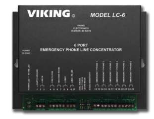
VIKING 6 Port Line Concentrator for Emergency Phones LC-6 User Guide
Designed, Manufactured and Supported in the USA


PRODUCT MANUAL
SECURITY & COMMUNICATION SOLUTIONS
LC-6 6 Port Line Concentrator for Emergency Phones January 4, 2021
Concentrate up to Six Emergency
Phones and Comply with ASME A17.1 Elevator Code

The LC-6 Line Concentrator eliminates the monthly charges for a dedicated line to each elevator. The LC-6 is designed to be used with the Viking 1600A Series Elevator Phones. Up to six of these emergency phones can communicate with authorized personnel on 3 other phones within a building, or add a telephone line to allow communication outside the building. A call initiated by an emergency phone can dial internally, externally, or both. Any other phones that are activated will be bridged with authorized personnel, thus fulfilling ASME A17.1 requirements.
All telephone line inbound calls are answered by the LC-6. A touch tone command will route the call to any of the phone ports. If no command is detected within 4 seconds, the call will be routed to the last emergency phone that was used. This allows emergency personnel to easily call back to the same phone.
Connections include a Fire Floor phone, a Machine Room phone and a Lobby phone. An output is also provided for driving up to three Viking LM-24D displays to show status of all ports.
Per ASME A17.1 requirements, the LC-6 can verify the operability of the telephone line on a daily basis and with the optional Viking model LV-1K line verification alarm panel, can display an “Elevator Communications Failure”.
Note: Per ASME A17.1 requirements, the LC-6 must be used with a battery backup (UPS) capable of keeping the LC6 running for up to 4 hours.
Features
- Connects up to (6) emergency phones
- Communicate with local and remote authorized personnel
- Automatic answering of inbound calls
- Touch Tone conferencing
- Separate Fire Floor phone port
- Machine Room phone and Lobby phone ports
- Accommodates the re-dialing feature of the Viking 1600A Series phones
- Programmable daily line verification check
Applications
- Elevator phones
- Emergency phones
- Area-of-Refuge phones
- E-30 courtesy phones
Specifications
Power: 120V AC/13.8V AC UL listed adapter provided
Dimensions: 8.25″ x 6.25″ x 1.75″ (210 mm x 159 mm x 45 mm)
Shipping Weight: 3.2 lbs. (1.5 kg)
Environmental: 32 F to 90 F (0 C to 32 C) with 5% to 95% non-condensing humidity
Maximum LM-24D Wire Length: 500 ft(152m) with #24 gauge wire
Maximum LV-1K Wire Length: 2000 ft (610m) with #24 gauge wire
Battery Backup: Greater than 4 hours when using
TRIPP-LITE model INTERNET550U (not included) Connections: 25 screw terminal block positions
www.vikingelectronics.com
Information: (715) 386-8861
Features Overview
IMPORTANT: Electronic devices are susceptible to lightning and power station electrical surges from both the AC outlet and the telephone line. It is recommended that a surge protector be installed to protect against such surges.

Installation

* TRIPP-LITE model INTERNET550U
This specific battery backup is chosen because it runs at a rated 99% efficiency. Battery backups that are not as efficient will waste battery power and not run as long. This TRIPP-LITE model INTERNET550U has been bench tested to run the LC-6 for more than 4 hours under the worst case condition (all 9 phones, the telephone line and display continuously in use). Other high efficiency battery backups with equal or longer runtime ratings are TRIPP-LITE models: INTERNET550SCR, INTERNET750U, ECO550UPS, ECO650UPS, ECO750UPS, ECO850UPS and AVR750U.
Programming
A. Accessing the Programming Mode
The LC-6 can be user programmed locally or remotely through a telephone lime from any touch tone phone.
- Locally with a Security Code
Step 1. Come off hook with a touch tone phone connected to the Fire Floor, Machine Room or Lobby phone, and wait for the beep. Step 2. Enter’*” followed by the 6-digit security code (factory set to 845464, see Programming section B). A double beep should then be heard indicating you have entered the programming mode. Step 3. When finished programming, hang up. - Locally without a Security Code
Step 1. Move DIP switch 3 to the ON position (Learn Mode, see Programming section J). Step 2. Come off hook with a touch tone phone connected to the Fire Floor. Machine Room or Lobby phone. A double beep will be heard indicating you have automatically entered the programming mode Step 3. When finished programming hang up and move DIP switch 3 back to the OFF position (Normal Operation Mode, see Programming section .1).. - Remotely using the Security Code
Step 1. From a touch tone phone call the telephone line attached to the LC-6.. Step 2. When the LC-6 answers, wait for the beep, then enter ‘*” followed by the 6-digit security code (factory set to 845464, see Programming section B). A double beep should then be heard indicating you have entered the programming mode. Step 3. When finished programming, hang up. - Remotely using the Security Code
Step 1. Move DIP switch 3 to the ON position (Learn Mode, see Programming section J).. Step 2. From a touch tone phone call the telephone line attached to the LC-6. Step 3. When the LC-6 answers, a double beep will be heard indicating you have automatcally entered the programming mode. Step 4. When finished programming hang up and move DIP switch 3 back to the OFF position (Normal Operation Mode,see Programming section .1). Warning: Failure to do step 4 above will cause the LC-6 to be stuck in the Learn Mode leaving many operational features not functional.
B. Programming the Security Code
The security code allows the user/installer to program the LC-6 while DIP switch 3 is in the OFF (normal operation) position. A six digit number is used to access the programming mode. The security code has been factory set to 845464 (V-I-K-I-N-G). It is recommended that you change the security code to your own 6 digit number as follows:
Step 1. Access programming as shown in section A. Step 2. Enter your new security code followed by #47. Step 3. When finished programming, hang up. Note: The security code must be six digits in length and MUST NOT contain a Q or #.
C. Quick Programming Features
Description
Description Enter Digits + Location Default Ring Assignment (factory set to cleared) none or 1 digit (0-6) + #44 Ring count ( factory set to 9 rings) 1 digits (0-9) + #45 Number of phones (factory set to 6 phones) 1 digits (1-6) + #46 Security Code (factory default = 845464) 6 digits (0-9) + #47 Disable dial 9 toggle feature (factory default) *0 Enable dial 9 toggle feature Q1 Exit programming and disconnect ##7 Reset all programming to factory default settings ### D. Default Ring Assignment (memory location #44)
Inbound telephone line calls are answered by the LC-6. After a single beep tone is heard, the caller can direct the call to any of the phones by entering a single touch tone command. This #44 memory location is used to tell the LC-6 how to default if the caller does not enter any touch tone command within 4 seconds of hearing the beep tone.
The factory setting is with the #44 memory location cleared (enter only #44 when programming), which means if no touch tone command is entered within 4 seconds, the LC-6 will default to re-ring the last emergency phone that was used. This enables emergency personnel to call back and automatically reach the specific emergency phone they had been talking to without the need to enter a touch tone command.
The LC-6 can be programmed so that if no touch tone command is given, to default to one of the six emergency phones by entering any digit 1 through 6 in the #44 memory location. Or enter “0#44” when programming so that if no inbound touch tone command is given, to default to ringing all emergency phones.E. Ring Count (memory location #45)
This location contains the number of times the LC-6 will ring the called device when a transfer is initiated. Entering a “0” count will disable the ring counter altogether and the port will continue to ring until answered or the caller hangs up. The factory default setting is “9” rings.F. Number of Phones (memory location #46)
This parameter is used so the LC-6 knows how many emergency phone ports to ring when the “All Call” feature is used. It is also how the line verification test knows how many emergency phone ports will be tested. For example, if only four Viking 1600A Series emergency phones are used, they are to be connected to emergency phone ports 1-4, and “4#46” should be entered in programming. The factory default setting is “6” emergency phones. Note: Be sure all emergency phones are set-up to answer an incoming call.G. Dial 9 Toggle Feature (Q1)
This feature is factory disabled (Q0) which means dialing a single touch tone “9” has only the ability to connect to the telephone line. When the dial 9 toggle feature is enabled (Q1), the LC-6 will have the ability to both connect and disconnect from the telephone line. In other words, dialing a touch tone “9” will toggle between connecting and disconnecting. Note: A minimum of 9 seconds must elapse after other touch tones have been dialed before “9” will be accepted as a disconnect command.See Operation section F for an example of how this feature might be used.H. Hang up (##7)
When programming the LC-6 from a remote location, this command can be used to cause an immediate hang up. This is useful if the LC-6 is being used on a phone line that does not issue a CPC signal when the distant party hangs up. In those cases, and if the ##7 command is not used, the LC-6 will still hang up, but after the programming time out of 20 seconds.I. Factory Reset all Programming (###)
When in programming, entering ### will reset all programming to the factory default settings.Switch Position Description 1 ON Emergency phones must dial 9 to connect to the telephone line (see description below) 1 OFF Emergency phones are directly connected to the phone line (factory setting) 2 ON Enable Line Verification test (see description on next page) 2 OFF Disable Line Verification test (factory setting) 3 ON Learn mode (see description below) 3 OFF Normal operation (factory setting) Switch 4 Switch 5 Description ON ON Normal audio detect sensitivity (factory setting) OFF OFF Increased audio detect sensitivity. Useful in applications in which voices or busy signals are having trouble breaking over the speaker when multiple emergency phones are in use at the same time. - DIP Switch 1 (Dial 9 mode)
Normally when an emergency phone comes off hook, it is immediately connected to the telephone line. In the Dial 9 mode, the emergency phone will be connected to an internal line, and a touch tone 9 is needed to connect to the outside telephone line. This feature must be used when the LC-6 is to be used for internal calls only and no telephone line is connected. The 9 must be followed by at least 3 seconds of silence so the LC-6 knows it is a transfer command and not part of a dialing string. Note: The internal line does not supply dial tone. - DIP Switch 2 (Line Verification Test)
When this switch is in the ON position, the daily line verification test feature is enabled. In accordance to ASME A17.1, once a day the LC-6 will check the telephone line for operable loop current. The LC-6 will also ring each of the assigned 1600A Series emergency phones (see Programming section F), to verify the operability of the lines running to each of the emergency phones, (and to be sure the emergency phone is capable of answering). See Operation section G for additional details. - DIP Switch 3 (Learn mode)
This DIP switch feature can be used when the user does not know the 6 digit touch tone security code needed to enter programming. When this switch is in the ON (Learn) position, the LC-6 will enter the programming mode immediately on an inbound call, or locally when a Fire Floor, Machine Room, or Lobby phone comes off hook. Once in programming a new security code can be programmed. Be sure to set this DIP switch to OFF (Normal Operation mode) when finished, so the LC-6 will operate properly.
Operation
The LC-6 allows voice communication from up to six Viking model 1600A Series emergency phones to a local Fire Floor phone, Machine Room phone and/or Lobby phone, as well as to an off premise phone through a telephone line. Any or all of the emergency phones can talk with any or all of the authorized personnel phones. Below is a simple directory of what to dial to call each of these devices, or access the telephone line.
A. Quick Directory
To Call: Dial:
Emergency phone 1, 2, 3, 4, 5, or 6 1, 2, 3, 4, 5, or 6
Fire Floor phone 7
Machine Room and Lobby phones 8
Access the telephone line 9
All Call (to call all emergency phones) 0
B. Emergency Phone Outbound Call
With DIP switch 1 OFF, when an emergency phone goes off hook, it will be directly connected to the telephone line so it can dial out for help. Alternatively, the emergency phone can be programmed to dial a single touch tone “7” to call the Fire Floor phone, or an “8” to ring both the Machine Room and Lobby phones. Since Viking 1600A Series emergency phones have the ability to dial additional phone numbers when the call is unanswered or gets a busy signal, the system can be set up so that a call for help first rings the local phone(s), then if unanswered, the 1600A Series phone can momentarily hang up and place an outside call to 911 or a Central Station Monitoring service.
With DIP switch 1 ON, when an emergency phone goes off hook, it will NOT be connected to the telephone line. Use this feature when the LC-6 is to be used for internal calls only and no telephone line is connected. When this is the case, the emergency phone can be programmed to dial a single touch tone “7” to call the Fire Floor phone, or an “8” to ring both the Machine Room and Lobby phones. If a telephone line is connected, the emergency phone can be programmed to place an outbound call by dialing a touch tone “9”, pause for four seconds, then dial the distant telephone number.
The LC-6 is not designed for one emergency phone to call or talk to another.
If additional emergency phones are activated while a call is in progress, they will be bridged to the existing authorized personnel.C. Inbound Call
When a call comes into the LC-6 on the telephone line, the LC-6 will answer after the first ring, give out a single “beep” tone, and listen for a touch tone command. A single touch tone 1 to 6 will cause the LC-6 to ring emergency phone 1 to 6; or dial a 0 to call all emergency phones. The LC-6 is factory set so that if no command is entered within 4 seconds, the LC-6 will re-ring the last emergency phone that was used, thus enabling emergency personnel to call back and automatically reach the specific emergency phone they had been talking to. The Fire Floor phone and Machine Room & Lobby phones can also be called into by dialing a single touch tone 7 or 8 respectively.D. Fire Floor Phone
When the Fire Floor phone goes off hook, the LC-6 will send a single beep. The user can then enter a touch tone 1 to 6 to call emergency phones 1 to 6, a touch tone 0 to call all emergency phones, or an 8 to call the Machine Room & Lobby phones. The Fire Floor phone can also dial “9” to access the telephone line to place an outbound call. While in use, if any other phone goes off hook, it will be instantly connected to the Fire Floor phone. Because of this, it is imperative the Fire Floor phone is not left off hook unattended.E. Machine Room and Lobby Phones
The Machine Room and Lobby phones work together. Inside the LC-6 they are connected to the same circuit. You can think of them as two phones in your house connected to the same phone line. An emergency phone that is programmed to dial a single touch tone “8” will have the advantage of ringing both phones, thus increasing the likelihood of being answered by local authorized personnel. When the Machine Room or Lobby phone goes off hook, the LC-6 will send a single beep. The user can then enter a touch tone 1 to 6 to call emergency phones 1 to 6, a touch tone 0 to call all emergency phones, or a 7 to call the Fire Floor phone. The Machine Room & Lobby phones can also dial “9” to access the telephone line to place an outbound call. While in use, if any other phone goes off hook, it will be instantly connected to the Machine Room & Lobby phones. Because of this, it is imperative the Machine Room & Lobby phones are not left off hook unattended.F. Touch Tone Conferencing Capability
Once an emergency phone, Fire Floor phone, Machine Room/Lobby Phone have established a call with another phone or the telephone line, a single touch tone can be dialed to conference in another phone. Once that phone has answered, another single touch tone can be dialed to conference in another phone and this process could be repeated until all phones are conferenced on the same call. Note: If an outgoing call is made on the telephone line, a minimum of 9 seconds must elapse after other touch tones have been dialed before the single touch tone will be accepted as a command to a conference in another phone.G. Dial “9” Access
The Fire Floor, Machine Room, or Lobby phones can dial 9 to access the telephone line to place an outside call. Alternatively, a single touch tone “9” can be used as a toggle function to either access the telephone line or disconnect from the telephone line (see Programming section G). Here is an example of how dialing 9 can be used to disconnect the telephone line. An emergency phone has placed a call through the LC-6’s telephone line to a 911 operator. A fireman arrives on the scene and joins the conversation from the Fire Floor phone. The fireman can then declare to the 911 operator that he is on site, and will take over. He can then dial a single touch tone 9 to drop the telephone line (hanging up on the 911 operator), and continue talking to the emergency phone.H. Line Verification Test
In accordance to ASME A17.1, the LC-6 has the ability to check the incoming telephone line for operability on a daily basis. The lines running from the LC-6 to each of the Viking 1600A Series emergency phones will also be tested at this same time. The LC-6 verifies the telephone line has loop current, and that each of the emergency phones will answer an incoming call. When a fault is detected, an audible and illuminated visual alarm showing “ELEVATOR COMMUNICATIONS FAILURE” will display on both the optional LM-24D displays and the optional LV-1K line verification alarm panel. Once the fault is corrected, the alarm state will clear within two minutes.I. LV-1K Line Verification Alarm Panel
The LC-6 has a two position terminal block for connection to an optional LV-1K line verification alarm panel. In accord-ance to ASME A17.1, the LV-1K has “ELEVATOR COMMUNICATIONS FAILURE” labeled in ¼” high letters, and will flash a red light and sound an audible signal every 30 seconds when a line verification fault is detected. The LV-1K line verification alarm panel can service a group of elevators controlled by a Fire Recall switch, and must be located in the vicinity of that switch and be visible to elevator users.J. LM-24 Displays
The LC-6 has a two position terminal block for connecting one or two optional Viking model LM24D displays. The optional displays provide a visual status of all the phones and the telephone line. When in use, the corresponding LED will light steady, and a ringing phone will show as a flashing LED. Emergency phones that are conference bridged into an existing emergency phone conversation, are displayed as a lit LED that winks once every few seconds.
The LM-24D displays will also show the testing status during the line verification tests. When all line verification tests pass, the “PASSED” LED will light. If a fault is found, the LM-24D displays will flash “ELEVATOR COMMUNICATIONS FAILURE” along with the line(s) that failed, and an audible signal tone will sound. The volume control on the front of the LM-24D display can be used to control the volume of the audible signal tone.
The optional LM-24D displays are useful for personnel using the Fire Floor phone, Machine Room phone, and/or Lobby phones. The LC-6 can power one or two LM-24D displays. Displays that are run greater than 400 ft (122 m) away may need a Viking model PS-2 12VDC power supply added for proper operation. With the power supply added, run lengths of up to 800 ft (244 m) can be achieved.
Fill out the LM-24D Identification Card as shown below:Warranty
IF YOU HAVE A PROBLEM WITH A VIKING PRODUCT, CONTACT: VIKING TECHNICAL SUPPORT AT (715) 386-8666
Our Technical Support Department is available for assistance Monday through Friday 8am – 5pm central time. So that we can give you better service, before you call please:- Know the model number, the serial number and what software version you have (see serial label).
- Have your Product Manual in front of you.
- It is best if you are on site.
RETURNING PRODUCT FOR REPAIR
The following procedure is for equipment that needs repair:- Customer must contact Viking’s Technical Support Department at 715-386-8666 to obtain a Return Authorization (RA) number. The customer MUST have a complete description of the problem, with all pertinent information regarding the defect, such as options set, conditions, symptoms, methods to duplicate problem, frequency of failure, etc.
- Packing: Return equipment in original box or in proper packing so that damage will not occur while in transit. Static sensitive equipment such as a circuit board should be in an anti-static bag, sandwiched between foam and individually boxed. All equipment should be wrapped to avoid packing material lodging in or sticking to the equipment. Include ALL parts of the equipment. C.O.D. or freight collect shipments cannot be accepted. Ship cartons prepaid to: Viking Electronics, 1531 Industrial Street, Hudson, WI 54016
- Return shipping address: Be sure to include your return shipping address inside the box. We cannot ship to a PO Box.
- RA number on carton: In large printing, write the R.A. number on the outside of each carton being returned.
RETURNING PRODUCT FOR EXCHANGE
The following procedure is for equipment that has failed out-of-box (within 10 days of purchase):- Customer must contact Viking’s Technical Support at 715-386-8666 to determine possible causes for the problem. The customer MUST be able to step through recommended tests for diagnosis.
- If the Technical Support Product Specialist determines that the equipment is defective based on the customer’s input and troubleshooting, a Return Authorization (R.A.) number will be issued. This number is valid for fourteen (14) calendar days from the date of issue.
- After obtaining the R.A. number, return the approved equipment to your distributor, referencing the R.A. number. Your distributor will then replace the Viking product using the same R.A. number.
- The distributor will NOT exchange this product without first obtaining the R.A. number from you. If you haven’t followed the steps listed in 1, 2 and 3, be aware that you will have to pay a restocking charge.
TWO YEAR LIMITED WARRANTY
Viking warrants its products to be free from defects in the workmanship or materials, under normal use and service, for a period of two years from the date of purchase from any authorized Viking distributor. If at any time during the warranty period, the product is deemed defective or malfunctions, return the product to Viking Electronics, Inc., 1531 Industrial Street, Hudson, WI., 54016. Customer must contact Viking’s Technical Support Department at 715-386-8666 to obtain a Return Authorization (R.A.) number.
This warranty does not cover any damage to the product due to lightning, over voltage, under voltage, accident, misuse, abuse, negligence or any damage caused by use of the product by the purchaser or others. This warranty does not cover non-EWP products that have been exposed to wet or corrosive environments. This warranty does not cover stainless steel surfaces that have not been properly maintained.
NO OTHER WARRANTIES. VIKING MAKES NO WARRANTIES RELATING TO ITS PRODUCTS OTHER THAN AS DESCRIBED ABOVE AND DISCLAIMS ANY EXPRESS OR IMPLIED WARRANTIES OR MERCHANTABILITY OR FITNESS FOR ANY PARTICULAR PURPOSE.
EXCLUSION OF CONSEQUENTIAL DAMAGES. VIKING SHALL NOT, UNDER ANY CIRCUMSTANCES, BE LIABLE TO PURCHASER, OR ANY OTHER PARTY, FOR CONSEQUENTIAL, INCIDENTAL, SPECIAL OR EXEMPLARY DAMAGES ARISING OUT OF OR RELATED TO THE SALE OR USE OF THE PRODUCT SOLD HEREUNDER.
EXCLUSIVE REMEDY AND LIMITATION OF LIABILITY. WHETHER IN AN ACTION BASED ON CONTRACT, TORT (INCLUDING NEGLIGENCE OR STRICT LIABILITY) OR ANY OTHER LEGAL THEORY, ANY LIABILITY OF VIKING SHALL BE LIMITED TO REPAIR OR REPLACEMENT OF THE PRODUCT, OR AT VIKING’S OPTION, REFUND OF THE PURCHASE PRICE AS THE EXCLUSIVE REMEDY AND ANY LIABILITY OF VIKING SHALL BE SO LIMITED. IT IS EXPRESSLY UNDERSTOOD AND AGREED THAT EACH AND EVERY PROVISION OF THIS AGREEMENT WHICH PROVIDES FOR DISCLAIMER OF WARRANTIES, EXCLUSION OF CONSEQUENTIAL DAMAGES, AND EXCLUSIVE REMEDY AND LIMITATION OF LIABILITY, ARE SEVERABLE FROM ANY OTHER PROVISION AND EACH PROVISION IS A SEPARABLE AND INDEPENDENT ELEMENT OF RISK ALLOCATION AND IS INTENDED TO BE ENFORCED AS SUCH.FCC REQUIREMENTS
This equipment complies with Part 68 of the FCC rules and the requirements adopted by the ACTA. On the side of this equipment is a label that contains, among other information, a product identifier in the format US:AAAEQ##TXXXX. If requested, this number must be provided to the telephone company.
The REN is used to determine the number of devices that may be connected to a telephone line. Excessive REN’s on a telephone line may result in the devices not ringing in response to an incoming call. In most but not all areas, the sum of the REN’s should not exceed five (5.0) To be certain of the number of devices that may be connected to a line, as determined by the total REN’s, contact the local telephone company. For products approved after July 23, 2001, the REN for this product is part of the product identifier that has the format US:AAAEQ##TXXXX. The digits represented by ## are the REN without a decimal point (e.g., 03 is a REN of 0.3). For earlier products, the REN is separately shown on the label.
The plug used to connect this equipment to the premises wiring and telephone network must comply with the applicable FCC Part 68 rules and requirements adopted by the ACTA. If your home has specially wired alarm equipment connected to the telephone line, ensure the installation of this LC-6 does not disable your alarm equipment. If you have questions about what will disable alarm equipment, consult your telephone company or a qualified installer.
If the LC-6 causes harm to the telephone network, the telephone company will notify you in advance that temporary discontinuance of service may be required. But if advance notice isn’t practical, the telephone company will notify the customer as soon as possible. Also, you will be advised of your right to file a complaint with the FCC if you believe it is necessary.
The telephone company may make changes in its facilities, equipment, operations, or procedures that could affect the operation of the equipment. If this happens, the telephone company will provide advance notice in order for you to make the necessary modifications to maintain uninterrupted service.If trouble is experienced with the LC-6, for repair or warranty information, please contact:
Viking Electronics, Inc., 1531 Industrial Street, Hudson, WI 54016 (715) 386-8666
If the equipment is causing harm to the telephone network, the telephone company may request that you disconnect the equipment until the problem is resolved.
Connection to Party Line Service is subject to State Tariffs. Contact the state public utility commission, public service commission or corporation commission for information.
WHEN PROGRAMMING EMERGENCY NUMBERS AND (OR) MAKING TEST CALLS TO EMERGENCY NUMBERS:
Remain on the line and briefly explain to the dispatcher the reason for the call. Perform such activities in the off-peak hours, such as early morning or late evenings.
It is recommended that the customer install an AC surge arrester in the AC outlet to which this device is connected. This is to avoid damaging the equipment caused by local lightning strikes and other electrical surges.PART 15 LIMITATIONS
This equipment has been tested and found to comply with the limits for a Class A digital device, pursuant to Part 15 of the FCC Rules. These limits are designed to provide reasonable protection against harmful interference when the equipment is operated in a commercial environment. This equipment generates, uses, and can radiate radio frequency energy and, if not installed and used in accordance with the instruction manual, may cause harmful interference to radio communications. Operation of this equipment in a residential area is likely to cause harmful interference in which case the user will be required to correct the interference at his own expense.Due to the dynamic nature of the product design, the information contained in this document is subject to change without notice. Viking Electronics, and its affiliates and/or subsidiaries assume no responsibility for errors and omissions contained in this information. Revisions of this document or new editions of it may be issued to incorporate such changes.
DOD# 245 12
Printed in the U.S.A.
ZF303220 REV A - DIP Switch 1 (Dial 9 mode)

