D-Link 5 Megapixel H.265 Outdoor Dome Network Camera DCS-6517 Installation Guide


Quick Installation Guide
5 Megapixel H.265 Outdoor Dome Network Camera

DCS-6517
Quick Installation Guide
This installation guide provides basic instructions for installing the DCS-6517. For additional information about how to use the camera, please see the User Manual which is available on the CD included in this package or from the D-Link support website.
Package Contents
- DCS-6517 5 Megapixel H.265 Outdoor Dome Network Camera
- Ethernet Cable
- Extension Adapter
- Mounting Plate and Screws
- Sun Shield
- Side Cover
- Alignment Sticker
- Manual and Software on CD-ROM
- Quick Installation Guide
If any of the above items are missing, please contact your reseller.
Safety Notice:
Installation and servicing should be done by certified technicians so as to conform to all local codes and prevent voiding your warranty.
D-Link DCS-6517 Quick Installation Guide
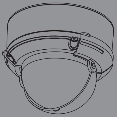
Hardware Overview

| 1 | IR LEDs | Provide illumination for low-light environments. | |
| 2 | Tilt Lock Screw | Can be loosened to adjust the camera’s tilt angle. | |
| 3 | Camera Lens | Camera lens to record video of the surrounding area. | |
| 4 | PowerlStatus LED | Indicates the camera’s current status. | |
| 5 | Light Sensor | Measures lighting conditions and switches between day and night mode accordingly. | |
| 6 | Horizontal Lock Screw | Can be loosened to adjust the horizontal rotation of the camera. | |
| 7 | microSD Card Slot | Accepts a microSD card for onboard storage of snapshots and video. | |
| 8 | Ethernet Jack | Connects to an RJ45 Ethernet port. Can be used with PoE to provide power to the camera. | |
| 9 | Cable Channels | Allow cables to exit the camera from the back or side. | |
| 10 | Cable Harness Port | Connects to the optional cable harness (not included). | |
| 1. 12V IN 2. GND 3. AUD IN 4. AUD GND 5. AUD OUT |
6. 12V OUT 7. GND 8. RESET 9. DI 10. DO | ||
Optional Cable Harness (not included)

| 11 | Cable Harness Connector | Connects to the DCS-6517. For more details on connecting the NV cable, refer to the User Manual. |
| 12 | DIIDO Connector | I/O connectors for external devices. (12 V DC output not supported for the DCS-6517) |
| 13 | Reset Button | Press and hold the button for 10 seconds to reset the camera back to the factory default settings. |
| 14 | 24 V Power Connector | Not supported for the DCS-6517. |
| 15 | Power Connector | Power connector for a 12 V DC power adapter (not included). |
| 16 | Audio Out (Green) | Connects to a speaker. |
| 17 | Audio In (Red) | Connects to a microphone. |
| 18 | BNC Connector | Not supported for the DCS-6517. |
Connecting the Optional Cable Harness
Remove the sun shield by lifting it off of the camera. Use the included security wrench to remove the 4 screws from the top of the camerathen remove the camera cover.


For side cable exit:
Attach the side cover via the provided screws.


For bottom cable exit:
Attach the protective side cover via the provided screws.

Connect the camera connector to the camera. Reattach the camera cover using the security wrench to tighten the 3 screws, and reattach the sun shield.

microSD Card Installation
Remove the sun shield by lifting it off of the camera. Use the included security wrench to remove the 4 screws from the top of the camera, then remove the camera cover.
Reattach the camera cover using the security wrench to tighten the 4 screws, and reattach the sun shield.


Mounting the Camera on the Ceiling
Locate a suitable position on the ceiling that is capable of supporting the weight of the camera. Attach the alignment sticker to the ceiling or wall.

Align the mounting plate to the drilled holes in the ceiling surface then tighten the screws.
Align the camera to the mounting plate and screw the camera body to the plate tightly.
Adjust the Camera’s Lens gimbal; turn the lens module left and right, up and down, and the orientation until the desired position is achieved. Tighten the pan, tile, and adjustment screw once completed.


Installing the Pendant Mount (Optional)
Attach the mounting plate to the bracket cap using the three included screws.

Locate a suitable position on the ceiling for a 34 mm (+2 / -0 mm) hole to be cut. Use the included template to mark and cut the mounting holes.

Drill four 6 mm holes corresponding to the holes in the mounting template and insert the plastic anchors into these holes.
Place the rubber seal between the pendant bracket and the ceiling to ensure a waterproof seal between the ceiling and the bracket.
Attach the pendant bracket to the ceiling using the screws provided.
Attach the bracket cap to the bottom of the pendant bracket by rotating the cap counterclockwise to tighten it into place.
Insert the screw into the base of the pendant bracket at the top of the bracket cap to secure the bracket cap into place.
Thread an Ethernet cable and the power cable through the pendant bracket.

Place the camera body onto the bracket cap and attach the dome to the base of the camera using the four long screws and the security screw.

Attach the mounting plate to the bracket cap using the included three screws.
Locate a suitable position on the ceiling for a 34 mm (+2 / -0 mm) hole to be cut. Use the included template to mark and cut the mounting holes.


Place the rubber seal between the right-angle bracket and the ceiling to ensure a waterproof seal between the ceiling and the bracket.
Attach the right-angle bracket to the ceiling using the screws provided.
Attach the bracket cap to the bottom of the right-angle bracket by rotating the cap counterclockwise to tighten it into place. Insert he screw into the base of the right-angle bracket at the top of the bracket cap to secure the bracket cap into place.
Thread an Ethernet cable and the power cable through the pendant bracket.
Place the camera body onto the bracket cap and attach the dome to the base of the camera using the three long screws and the security screw.


Connecting the Camera
Connection with a PoE Switch
• Connect the Ethernet cable to your PoE switch or injector. The Ethernet cable will provide the camera with both power and a network connection.

If you have the optional cable harness, you can also use the following connection method:

General Connection Using 12 V DC Power
Adapter (not included)
- Connect the Ethernet cable to your network.
- Connect your power adapter to the camera’s power connector, then plug in the power adapter.
Configuring the Camera
insert the DCS-6517 CD into your computer’s CD-ROM drive to begin the installation. If the Autorun function on your computer is disabled, or if the D-Link Launcher fails to start automatically, run D:\autorun.exe, where D: represents the drive letter of your CD-ROM drive.

After clicking Setup Wizard, the following window will open.


Viewing Your Camera via a Web Browser
Click on the D-Link Setup Wizard SE icon that was created in your Windows Start menu (Start > D-Link > Setup Wizard SE).

Select the camera and click Link to access the web configuration.
The Setup Wizard will automatically open your web browser to the IP address of the camera.

The first time you connect to the camera, you will be asked to set a password for the administrator account. After entering a password, click Save.

The camera’s live video page will open, and you can now control and configure your camera. For additional information about web configuration, please refer to the user manual, which is available on the D-Link website.
