Dell EMC Networking Switch S4148-ON/S4128-ON User Manual

Switch Configuration Guide for Dell EMC SC Series SANs

Abstract
This document illustrates how to configure Dell EMC™ Networking S4148-ON and S4128-ON switches for use with Dell EMC SC Series storage using Dell EMC best practices.
October 2017
Dell EMC Configuration and Deployment Guide
Revisions
| Date | Revision |
| Oct-17 | Initial release |
The information in this publication is provided “as is.” Dell Inc. makes no representations or warranties of any kind with respect to the information in this publication and specifically disclaims implied warranties of merchantability or fitness for a particular purpose.
Use, copying, and distribution of any software described in this publication require an applicable software license.
© 2017 Dell Inc. or its subsidiaries. All Rights Reserved. Dell, EMC, Dell EMC, and other trademarks are trademarks of Dell Inc. or its subsidiaries. Other trademarks may be trademarks of their respective owners.
Dell believes the information in this document is accurate as of its publication date. The information is subject to change without notice.
Introduction
This document illustrates how to configure Dell EMC™ Networking S4148-ON and S4128-ON switches for use with Dell EMC SC Series storage using Dell EMC best practices.
The host servers and storage controllers can be connected to the switches using the QSFP+ and QSFP28 ports with appropriate breakout cables. The switches are interconnected to each other using 40GbE cables or 100GbE cables.
Optional steps are provided in section 3 to enable Data Center Bridging (DCB).
For more information on SC Series SAN design recommendations, see the Storage Center System Manager Administrator’s Guide and the Storage Center Deployment Guide at the Customer Portal (login required).
1.1 Document conventions
Table 1 lists the formatting conventions used in this document.
Table1 Document conventions
Format |
Description | Example |
| Bold | User input | OS# show version |
| Bold Italic | User input (variable) | OS# my password |
| <Italic> <brackets> | Separate variables | <lp address> <mask> |
1.2 Audience
This switch configuration guide describes an optimal configuration following Dell EMC’s best practices for a SC Series iSCSI SAN and is intended for storage or network administrators and deployment personnel.
1.3 Switch details
Table 2 provides an overview of the switch configuration.
Table 2 Switch specifications
Dell EMC Networking S4148-0N/S4128-ON | |
| Switch vendor | Dell EMC |
| Switch model | S4148U-ON, S4148F-ON, S4148FE-ON, S4148T-ON, S4128FON, and S4128T-ON |
| Switch firmware | 10.3.1 or later |
Note: For proper functionality, the switch must be at the switch firmware version shown in Table 2 before proceeding with this configuration. Using previous firmware versions may have unpredictable results.
Note: The latest firmware updates and documentation can be found at Dell.com/support.
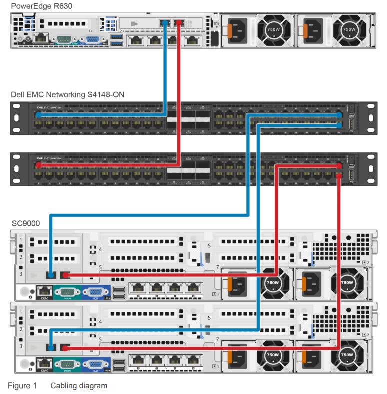
1.4 Cabling diagram
The cabling diagram shown in Figure 1 represents the Dell EMC recommended method for deploying servers and SC Series arrays.

Dell EMC recommended switch configuration
The steps in this section show how to configure two Dell EMC Networking S4148-ON/S4128-ON switches in the Dell SC series storage environment.
Note: The configuration steps in this section are only recommended when the switch is used as a dedicated SAN for iSCSI traffic.
2.1 Hardware configuration
- Power on the two switches.
- Connect a serial cable to the serial port of the first switch.
- Using PuTTY or another terminal utility, open a serial connection session to the switch.
- Open the terminal emulator and configure it to use the serial port (COM1, COM2). Configure serial communications for 115200 N,8,1, and no flow control.
Note: This example assumes a switch at its default configuration settings. Always back up the configuration settings prior to performing any configuration changes.
2.1 Check the firmware version
OS10# show version
Note: If the active version displayed here is not 10.3.1.x or later, visit Dell.com/support and download the latest update for the switches.
2.2 Delete the startup configuration
Note: The following commands will delete all configuration settings.
OS10# delete startup-configuration
Proceed to delete startup-config [confirm yes/no(default)]yes
OS10# reload
System configuration has been modified. Save? [yes/no]no
Proceed to reboot the system? [confirm yes/no]yes
Note: The switch will reboot. After the startup configuration is deleted, the factory default password is admin.
2.3 Switch profiles (only for S4148-ON and its variants)
On the S4148-ON switch and its variants, switch port profiles determine the available front-panel Ethernet ports and supported breakout interfaces on uplink ports. Refer to the switch user’s guide to determine which switch profile fits your environment.
Note: Changing switch profiles will delete all configuration information from the switch except for the management port configuration. Save and reload the switch for the new switch profile to take effect.
OS10# configure terminal
OS10(config)# switch-port-profile 1/1 profile-<number>
Warning: Switch port profile will be applied only after a save and reload. All
management port configurations will be retained but all other configurations
will be wiped out after the reload.
OS10(config)# exit
OS10# copy running-configuration startup-configurationOS10# reloadProceed to reboot the system? [confirm yes/no]yes
2.4 Configure unified ports on S4148U-ON
Note: This section applies to the S4148U-ON switch only. Skip this section if using other switches.
This section configures unified ports on S4148U-ON switches to Ethernet ports. Refer to the switch user’s guide for further details. Port-group 1/1/1-1/1/6 refers to the first 24 SFP+ ports on the switch. Use the following commands to convert these ports to Ethernet ports.
OS10# configure terminal
OS10(config)# port-group 1/1/<port-group-number>
OS10(conf-pg-1/1/1)# mode Eth 10g-4xOS10(conf-pg-1/1/1)# exit
OS10(config)#
Repeat the prior steps for port-group 1/1/1 to 1/1/6.
Note: QSFP+ and QSFP28 ports are by default in Ethernet mode. They can be configured by configuring port-group 1/1/7-1/1/10 using the prior commands. Refer to the S4148-ON switch user’s guide for more information.
2.5 Configure out of band (OOB) management port
OS10(config)# interface mgmt 1/1/1
OS10(conf-if-ma-1/1/1)# no ip address dhcp
OS10(conf-if-ma-1/1/1)# ip address <ipaddress>/<subnet>
OS10(conf-if-ma-1/1/1)# exit
OS10(config)#
2.6 Configure login credentials
OS10(config)# username admin password $0$<password>
2.7 Configure QSPF+ and QSFP28 ports to 4 x 10GbE breakout ports
QSFP+ and QSFP28 ports on S4148-ON and S4128-ON switches can be configured as breakouts to be used with 10GbE iSCSI storage or server network adapters. To configure these ports as 4 x 10GbE ports, use the following commands.
OS10(config)# interface breakout 1/1/<port-number> map 10g-4x
OS10(config)# exit
OS10#
Use the following command to check the port interface status:
OS10# show interface status
2.8 Enable switch ports
Switch ports are enabled and are configured switch port mode access by default for S4148-ON and S4128-ON switches. If choosing to reconfigure the ports, use the following steps.
Option 1: Enable ports individually by entering the port number.
OS10# configure terminal
OS10(config)#interface ethernet 1/1/1
Note: For ports configured as 4 x 10GbE breakout ports, use the following command in which 1/1 represents the switch number, xx represents a port number, and yy represents sub port number:
OS10(conf)#interface ethernet 1/1/xx:yy
OS10(conf-if-eth1/1/1)# switchport mode access
OS10(conf-if-eth1/1/1)# no shutdown
OS10(conf-if-eth1/1/1)# exit
Option 2: Enable multiple ports at once using the range parameter.
OS10# configure terminal
OS10(config)# interface range ethernet 1/1/1–1/1/54
Note: For ports configured as 4 x 10GbE breakout ports, use the following command in which 1/1 represents the switch number, xx represents port number, and yy represents sub port number:
OS10(conf)#interface range ethernet 1/1/xx:yy-1/1/xx:yy
OS10(conf-range-eth1/1/1-1/1/54)# switchport mode access
OS10(conf-range-eth1/1/1-1/1/54)# no shutdown
OS10(conf-range-eth1/1/1-1/1/54)# exit
2.9 iSCSI enable
The steps in this section enable iSCSI auto-detection of attached storage arrays and switch autoconfiguration.
Dell PS Series and SC Series storage arrays are detected by the switch when iscsi is enabled. The switch will auto-configure for Jumbo frames with MTU 9216 and flowcontrol receive on, and transmit off for all the ports. The ports detected to be connected to the storage units are auto-configured as spanning-tree edge ports with unicast storm control disabled.
OS10(config)# iscsi enable
OS10(config)# iscsi session-monitoring enable
Note: Do not change the LLDP description on the SC Series array. Changing this will disable iSCSI storage detection and iSCSI auto-configuration.
Note: iSCSI auto-configuration on OS10 switch ports is not supported with QLogic® QLE4062 network adapters on SC Series arrays.
2.10 Enable Jumbo frames and flow control (optional)
Note: This step is optional because iSCSI auto-detection and auto-configuration enabled in the previous step will enable Jumbo frames with MTU 9216 and enable receive flow control on all ports, once PS Series or SC Series storage ports are detected on the switch.
OS10(config)# interface range ethernet 1/1/1 – 1/1/54
OS10(conf-range-eth1/1/1-1/1/54)# mtu 9216
OS10(conf-range-eth1/1/1-1/1/54)# flowcontrol receive on
OS10(conf-range-eth1/1/1-1/1/54)# flowcontrol transmit off
2.11 Configure spanning tree on edge ports
OS10(conf-range-eth1/1/1-1/1/54)# spanning-tree port type edge
OS10(conf-range-eth1/1/1-1/1/54)# exit
Note: Spanning tree is enabled by default. If there is a need to reconfigure it, use the following command.
OS10(config)# no spanning-tree disable
OS10(config)# exit
2.12 Save configuration
OS10# copy running-configuration startup-configuration
OS10# reload
System configuration has been modified. Save? [yes/no]: yesProceed to reboot the system? [confirm yes/no]:yes
2.13 Configure additional switch
Repeat the commands from section 2 to configure the second switch.
Note: The preceding procedure places all switch ports in the default VLAN. If preferring to place ports in a non-default VLAN, refer to the switch documentation.
Configure Data Center Bridging (DCB) (optional)
To enable DCB mode on the switch, use the commands in this section.
Note: Complete the switch configuration steps in section 2 before configuring the switch for DCB mode.
Note: DCB switch configuration is applicable only for environments with DCB-capable SC Series arrays.
3.1 Disable iSCSI
OS10# configure terminal
OS10(config)# no iscsi enable
OS10(config)# no iscsi session-monitoring enable
3.2 Disable 802.3x flow control on all ports
OS10# configure terminal
OS10(config)# interface range ethernet 1/1/1–1/1/54OS10(conf-range-eth1/1/1-1/1/54)# no flowcontrol receive
OS10(conf-range-eth1/1/1-1/1/54)# no flowcontrol transmit
OS10(conf-range-eth1/1/1-1/1/54)# exit
OS10(config)#
3.3 Enable DCB
OS10(config)# dcbx enable
3.4 Create tagged VLAN for all ports and port-channels
Note: You must supply a VLAN ID. The valid range is 2-4093.
The following commands configure a single VLAN ID. If desired, multiple VLAN IDs can be created on the switch and assigned to ports.
OS10(config)# interface vlan <vlan-id>OS10(conf-if-vl-<vlan-id>)# mtu 9216
OS10(conf-if-vl-<vlan-id>)# no shutdown
OS10(conf-if-vl-<vlan-id>)# exit
3.5 Create QoS policy-map with dot1p values as trusted
OS10(config)# policy-map type qos <trust-policy-map-name>
OS10(config-pmap-qos)# class class-trust
OS10(config-pmap-c-qos)# trust dot1p
OS10(config-pmap-c-qos)# exit
OS10(config-pmap-qos)# exit
OS10(config)#
3.6 Create PFC dot1p traffic class
The following commands configure a network QoS class-map and match the iSCSI traffic class.
OS10(config)# class-map type network-qos <iSCSI-class-map-name>
OS10 (config-cmap-nqos)# match qos-group 4
OS10 (config-cmap-nqos)# exit
OS10(config)#
3.7 Configure network QoS policy map
OS10(config)# policy-map type network-qos <policy-map-name>
OS10(config-pmap-network-qos)# class <iSCSI-class-map-name>
OS10 (config-pmap-c-nqos)# pause
OS10 (config-pmap-c-nqos)# pfc-cos 4
OS10 (config-pmap-c-nqos)# exit
OS10(config-pmap-network-qos)# exit
OS10(config)#OS10(config)# policy-map type application <qos-policy-map-name>
OS10(config-pmap-application)# class class-iscsi
OS10 (config-pmap-c-app)# set qos-group 4
OS10 (config-pmap-c-app)# set cos 4
OS10 (config-pmap-c-app)# exit
OS10(config-pmap-application)# exit
OS10(config)#
3.8 Configure ETS policies
OS10(config)# qos-map traffic-class <queue-map-name>
OS10(config-qos-map)# queue 0 qos-group 0-3,5-7
OS10(config-qos-map)# queue 4 qos-group 4
OS10(config-qos-map)# exit
OS10(config)#OS10(config)# class-map type queuing <LAN-traffic-map-name>
OS10(config-cmap-queuing)# match queue 0
OS10(config-cmap-queuing)# exit
OS10(config)#OS10(config)# class-map type queuing <iSCSI-traffic-map-name>
OS10(config-cmap-queuing)# match queue 4
OS10(config-cmap-queuing)# exit
OS10(config)#
3.9 Create an ETS policy map for bandwidth allocations
OS10(config)# policy-map type queuing <queuing-policy-name>
OS10(config-pmap-queuing)# class <LAN-traffic-map-name>
OS10(config-pmap-c-que)# bandwidth percent <bandwidth-percentage>
OS10(config-pmap-c-que)# class <iSCSI-traffic-map-name>
OS10(config-pmap-c-que)# bandwidth percent <bandwidth-percentage>
OS10(config-pmap-c-que)# exit
OS10(config-pmap-queuing)# exit
OS10(config)#
Note: The sum of the bandwidth percentages must equal 100. Monitor the LAN and SAN performance in your environment to determine optimal bandwidth settings.
3.10 QoS policy
OS10(config)# system QoS
OS10(config-sys-qos)# service-policy input type qos <trust-policy-map-name>
OS10(config-sys-qos)# service-policy type application <qos-policy-map-name>
OS10(config-sys-qos)# ets mode on
OS10(config-sys-qos)# exit
OS10(config)#
3.11 Apply policies and VLAN ID to all switch edge ports
OS10(config)# interface range ethernet 1/1/1-1/1/54
OS10(conf-range-eth1/1/1-1/1/54)# switchport mode trunk
OS10(conf-range-eth1/1/1-1/1/54)# switchport trunk allowed vlan <vlan-id>
OS10(conf-range-eth1/1/1-1/1/54)# service-policy input type network-qos <policymap-name>
OS10(conf-range-eth1/1/1-1/1/54)# service-policy output type queuing <queuingpolicy-name>
OS10(conf-range-eth1/1/1-1/1/54)# ets mode on
OS10(conf-range-eth1/1/1-1/1/54)# qos-map traffic-class <queue-map-name>
OS10(conf-range-eth1/1/1-1/1/54)# priority-flow-control mode on
OS10(conf-range-eth1/1/1-1/1/54)# exitOS10(config)#
3.12 iSCSI enable
OS10(config)# iscsi enable
OS10(config)# iscsi session-monitoring enableOS10(config)# exit
3.13 Save configuration
OS10# copy running-configuration startup-configuration
3.14 Show commands to verify DCBx, ETS, and PFC status on individual ports
OS10# show lldp dcbx interface ethernet 1/1/<port-number>
OS10# show lldp dcbx interface ethernet 1/1/<port-number> pfc detailOS10# show lldp dcbx interface ethernet 1/1/<port-number> ets detail
3.15 Configure additional switches
Repeat the commands from section 3 to configure DCB on additional switches.
Revert from DCB to non-DCB configuration (optional)
One method to revert from a DCB configured switch to a non-DCB configured switch is to delete the current configuration (startup-config) and follow the steps in section 2. If deleting the current configuration is not an option, use the following procedure to unconfigure DCB and enable standard flow control.
Note: This is a disruptive operation that requires downtime. The arrays will temporarily lose communication with each other. Power off all arrays and hosts connected to the SAN before proceeding with these steps.
4.1 Disable DCB
OS10# configure terminalOS10(config)# no dcbx enableOS10(config)#
4.2 Disable iSCSI
OS10(config)# no iscsi enable
OS10(config)# no iscsi session-monitoring enable
4.3 Remove DCB policies and apply standard flow control on edge ports
OS10(config)# interface range ethernet 1/1/1-1/1/54
OS10(conf-range-eth1/1/1-1/1/54)# no priority-flow-control
OS10(conf-range-eth1/1/1-1/1/54)# no qos-map traffic-classOS10(conf-range-eth1/1/1-1/1/54)# no etsOS10(conf-range-eth1/1/1-1/1/54)# no service-policy output type queuing <queuing-policy-name>
OS10(conf-range-eth1/1/1-1/1/54)# no service-policy input type network-qos <policy-map-name>
OS10(conf-range-eth1/1/1-1/1/54)# no switchport trunk allowed vlan <vlan-id>OS10(conf-range-eth1/1/1-1/1/54)# no switchport mode
OS10(conf-range-eth1/1/1-1/1/54)# switchport mode access
OS10(conf-range-eth1/1/1-1/1/54)# flowcontrol receive on
OS10(conf-range-eth1/1/1-1/1/54)# flowcontrol transmit off
OS10(conf-range-eth1/1/1-1/1/54)# exit
OS10(config)#
4.4 Revert to default VLAN ID on switch and arrays
Once DCB is disabled on the switch, the SC Series arrays will no longer use the VLAN ID that was configured when DCB was enabled. The arrays will revert to the default or native VLAN. Therefore, a valid VLAN must be configured for all host servers, switches, and SC Series array members. A valid VLAN can use the default or native VLAN ID (typically 0 or 1), or a specific VLAN can be configured (for example, VLAN 100). If a non-default VLAN is configured, any ports connected to the arrays must be configured as untagged.
The steps in section 4.3 revert the switch ports to default native VLAN 1. Use the following command to remove VLANs other than VLAN 1 from the switch configuration.
OS10(config)# no interface vlan <vlan-id>
4.5 Remove ETS, PFC, and other policies from the switch configuration
OS10(config)# no policy-map type queuing <queuing-policy-name>
OS10(config)# no class-map type queuing <LAN-traffic-map-name>
OS10(config)# no class-map type queuing <iSCSI-traffic-map-name>
OS10(config)# system qosOS10(config-sys-qos)# no etsOS10(config-sys-qos)# no service-policy input type qos <trust-policy-map-name>
OS10(config-sys-qos)# no service-policy type application <qos-policy-map-name>
OS10(config-sys-qos)# exit
OS10(config)# no policy-map type network-qos <policy-map-name>
OS10(config)# no policy-map type qos <trust-policy-map-name>
OS10(config)# policy-map type application <qos-policy-map-name>
OS10(config-pmap-application)# no class class-iscsi
OS10(config-pmap-application)# exit
OS10(config)# no qos-map traffic-class <queue-map-name>
OS10(config)# no class-map type network-qos <iSCSI-class-map-name>
OS10(config)# no class-map type application <qos-policy-map-name>
OS10(config)#
4.6 iSCSI enable
OS10(config)# iscsi enable
OS10(config)# iscsi session-monitoring enableOS10(config)# exit
4.7 Save configuration
OS10# copy running-configuration startup-configuration
4.8 Reload
OS10# reload
Proceed to reboot the system? [confirm yes/no]:yes
Note: The switch will reboot.
4.9Verify DCB status
OS10# show lldp dcbx interface ethernet 1/1/<port-number>
4.10 Configure additional switch
Repeat the commands from section 4 to disable DCB on additional switches.
A. Technical support and resources
Dell.com/support is focused on meeting customer needs with proven services and support.
Dell TechCenter is an online technical community where IT professionals have access to numerous resources for Dell EMC software, hardware, and services.
Storage Solutions Technical Documents on Dell TechCenter provide the expertise that helps to ensure customer success on Dell EMC storage platforms.
A.1 Related resources
Referenced or recommended publications:
Dell EMC Storage Compatibility Matrix
For SC Series best practices white papers, reference architectures, and sizing guidelines for enterprise applications and SANs, refer to SC Series Technical Documents.
SCG3704