Makita LW1400 14 Inch Cut-off Saw with Tool-Less Wheel Change Instruction Manual


INSTRUCTION MANUAL
Portable Cut-Off
LW1400 LW1401


IMPORTANT: Read Before Using.
Original instructions
SPECIFICATIONS
| Model: | LW1400 | LW1401 | |
| Wheel diameter | 355 mm (14″) | ||
| Hole diameter | 25.4 mm (1″) | ||
| No load speed | 3,800 /min | ||
| Dimensions (LxWx H) | With European type safety guard | 530 mm x 295 mm x 640 mm (20-7/8″ x 11-5/8 x 25-1/4″) |
500 mm x 295 mm x 640 mm (19-3/4″ x 11-5/8″ x 25-1/4″) |
| With safety guard other than European type | 530 mm x 290 mm x 640 mm (20-7/8″ x 11-3/8″ x 25-1/4″) |
500 mm x 290 mm x 620 mm (19-3/4″ x 11-3/8″ x 24-3/8″) | |
| Net weight | With European type safety guard and under cover | 17.2 kg (37.9 Ibs) | 16.8 kg (37.0 Ibs) |
| Safety class | |||

- Due to our continuing program of research and development, the specifications herein are subject to change without notice.
- Specifications may differ from country to country.
- Weight according to EPTA-Procedure 01/2003
- The shape and weight vary depending on the specifications which differ country to country.
For your own safety, read instruction manual before operating tool. Save it for future reference.
General safety precautions (For all tools)
- KNOW YOUR POWER TOOL. Read the owner’s manual carefully. Learn the tool’s applications and limitations, as well as the specific potential hazards peculiar to it.
- KEEP GUARDS IN PLACE and in working order.
- REMOVE ADJUSTING KEYS AND WRENCHES. Form habit of checking to see that keys and adjusting wrenches are removed from tool before turning it on.
- KEEP WORK AREA CLEAN. Cluttered areas and benches invite accidents.
- DO NOT USE IN DANGEROUS ENVIRONMENT. Do not use power tools in damp or wet locations, or expose them to rain. Keep work area well lighted. Do not use tool in presence of flammable liquids or gases.
- KEEP CHILDREN AWAY. All visitors should be kept safe distance from work area.
- MAKE WORKSHOP KID PROOF with padlocks, master switches, or by removing starter keys.
- DO NOT FORCE TOOL. It will do the job better and safer at the rate for which it was designed.
- USE RIGHT TOOL. Do not force tool or attachment to do a job for which it was not designed.
- WEAR PROPER APPAREL. Do not wear loose clothing, gloves, neckties, rings, bracelets, or other jewelry which may get caught in moving parts. Nonslip footwear is recommended. Wear protective hair covering to contain long hair.
- ALWAYS USE SAFETY GLASSES. Also use face or dust mask if cutting operation is dusty. Everyday eyeglasses only have impact resistant lenses, they are NOT safety glasses.
- SECURE WORK. Use clamps or a vise to hold work when practical. It’s safer than using your hand and it frees both hands to operate tool.
- DO NOT OVERREACH. Keep proper footing and balance at all times.
- MAINTAIN TOOLS WITH CARE. Keep tools sharp and clean for best and safest performance. Follow instructions for lubricating and changing accessories.
- DISCONNECT TOOLS before servicing; when changing accessories such as blades, bits, cutters, and the like.
- REDUCE THE RISK OF UNINTENTIONAL STARTING. Make sure switch is in off position before plugging in.
- USE RECOMMENDED ACCESSORIES. Consult the owner’s manual for recommended accessories. The use of improper accessories may cause risk of injury to persons.
- NEVER STAND ON TOOL. Serious injury could occur if the tool is tipped or if the cutting tool is unintentionally contacted.
- CHECK DAMAGED PARTS. Before further use of the tool, a guard or other part that is damaged should be carefully checked to determine that it will operate properly and perform its intended function – check for alignment of moving parts, binding of moving parts, breakage of parts, mounting, and any other conditions that may affect its operation. A guard or other part that is damaged should be properly repaired or replaced.
- DIRECTION OF FEED. Feed work into a blade or cutter against the direction of rotation of the blade or cutter only.
- NEVER LEAVE TOOL RUNNING UNATTENDED. TURN POWER OFF. Do not leave tool until it comes to a complete stop.
- REPLACEMENT PARTS. When servicing, use only identical replacement parts.
- POLARIZED PLUGS. To reduce the risk of electric shock, this equipment has a polarized plug (one blade is wider than the other). This plug will fit in a polarized outlet only one way. If the plug does not fit fully in the outlet, reverse the plug. If it still does not fit, contact a qualified electrician to install the proper outlet. Do not change the plug in any way.
VOLTAGE WARNING: Before connecting the tool to a power source (receptacle, outlet, etc.) be sure the voltage supplied is the same as that specified on the nameplate of the tool. A power source with voltage greater than that specified for the tool can result in SERIOUS INJURY to the user- as well as damage to the tool. If in doubt, DO NOT PLUG IN THE TOOL. Using a power source with voltage less than the nameplate rating is harmful to the motor.
USE PROPER EXTENSION CORD. Make sure your extension cord is in good condition. When using an extension cord, be sure to use one heavy enough to carry the current your product will draw. An undersized cord will cause a drop in line voltage resulting in loss of power and overheating. Table 1 shows the correct size to use depending on cord length and nameplate ampere rating. If in doubt, use the next heavier gage. The smaller the gage number, the heavier the cord.
Table 1: Minimum gage for cord
| Ampere Rating | Volts | Total length of cord in feet | ||||||||
| 120V | 25 ft. | 50 ft. | 100 ft. | 150 ft. | ||||||
| 220V – 240V | 50 ft. | 100 ft. | 200 ft. | 300 ft. | ||||||
| More Than | Not More Than | AWG | ||||||||
| 0 | 6 | — | 18 | 16 | 16 | 14 | ||||
| 18 | 16 | 14 | 12 | |||||||
| 6 | 10 | |||||||||
| 16 | 16 | 14 | 12 | |||||||
| 10 | 12 | |||||||||
| 14 | 12 | Not Recommended | ||||||||
| 12 | 16 | |||||||||
Specific safety rules
DO NOT let comfort or familiarity with product (gained from repeated use) replace strict adherence to portable cut-off safety rules. If you use this tool unsafely or incorrectly, you can suffer serious personal injury.
- Wear hearing protection during extended period of operation.
- Use only wheels having a maximum operating speed at least as high as “No Load RPM” marked on the tool’s nameplate. Use only fiberglass-reinforced cut-off wheels.
- Check the wheel carefully for cracks or damage before operation. Replace cracked or damaged wheel immediately. Run the tool (with guard) at no load for about a minute, holding tool away from others. If wheel is flawed, it will likely separate during this test.
- Secure the wheel carefully.
- Use only flanges specified for this tool.
- Be careful not to damage the spindle, flanges
(especially the installing surface) or bolt. Damage to these parts could result in wheel breakage. - Do not operate the tool without guards in place. Check wheel guard for proper closing before each use. Do not operate the tool if wheel guard does not move freely and close instantly. Never clamp or tie the wheel guard into the open position.
- Hold the handle firmly.
- Keep hands away from rotating parts.
- Make sure the wheel is not contacting the workpiece before the switch is turned on.
- Before using the tool on an actual workpiece, let it run for a while. Watch for vibration or wobbling that could indicate poor installation or a poorly balanced wheel.
- Watch out for flying sparks when operating. They can cause injury or ignite combustible materials.
- Remove material or debris from the area that might be ignited by sparks. Be sure that others are not in the path of the sparks. Keep a proper, charged fire extinguisher closely available.
- Use the cutting edge of the wheel only. Never use side surface.
- Do not attempt to keep the trigger in the ON position.
- If the wheel stops during operation, makes an odd noise or begins to vibrate, switch off the tool immediately.
- Turn off the tool and wait for the wheel to stop before moving workpiece or changing settings.
- Do not touch the workpiece immediately after operation; it is extremely hot and could burn your skin.
- Store wheels in a dry location only.
SAVE THESE INSTRUCTIONS.

Symbols
The followings show the symbols used for tool.
| V | volts |
| A | amperes |
| Hz | hertz |
| alternating current | |
| Class II Construction | |
| revolutions or reciprocation per minute |


INSTALLATION
Securing the base
This tool should be bolted with two bolts to a level and stable surface using the bolt holes provided in the tool’s base. This will help prevent tipping over and possible personal injury.

FUNCTIONAL DESCRIPTION
Unlocking/locking tool head
The tool head can be locked. Always lock the tool head when not in use or carrying.
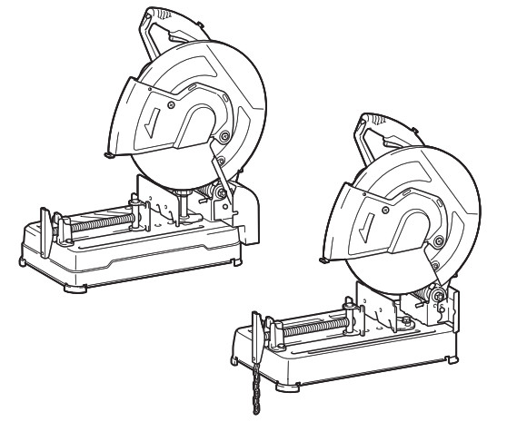
For LW1400
To unlock, depress the tool head slightly and push the lock pin. To lock, return the lock pin while holding down the tool head.

For LW1401
Unhook the lock chain from the hook. Always hook the lock chain to the hook when not in use.

WARNING: Before plugging in the tool, always check to see that the switch trigger actuates properly and returns to the “OFF” position when released.

To prevent the switch trigger from being accidentally pulled, a lock-off button is provided. To start the tool, press the lock-off button and pull the switch trigger. Release the switch trigger to stop.
NOTICE: Do not pull the switch trigger hard without pressing in the lock-off button. This can cause switch breakage.
Interval between vise and guide plate
The following interval settings of the vise are available:
- 0 – 170 mm (0- 6-11/16) (original setting)
- 35 – 205 mm (1-3/8- 8-1/16)
- 70 – 240 mm (2-3/4- 9-7/16)
If your work requires different setting, proceed as follows to change the spacing or interval.
For LW1400
Loosen the screw on the guide plate. Move the guide plate to the desired position then tighten the screw.

For LW1401
Remove the two hex bolts using a socket wrench. Move the guide plate to the desired position and secure it with the hex bolts.

Cutting angle adjustment
For LW1400
Turn the lever counterclockwise. Move the guide plate to the desired angle and fully tighten the lever.

For LW1401
NOTICE: When performing right miter cut, always set the guide plate at 0 – 170 mm (06-11/16) position. Setting at the 35 – 205 mm (1-3/8- 8-1/16) or 70 – 240 mm (2-3/4- 9-7/16) position hinders the movement of stopper plate, which results in a failure cut.
Loosen the two hex bolts using a socket wrench. Turn the guide plate to the desired angle and secure it with the hex bolts. Be careful not to move the set angle while securing the hex bolts.

NOTE: The scale on the guide plate is only a rough indication. For more accurate angle, use a protractor or triangle ruler. Keep the handle down so that the cut-off wheel extends into the base. At the same time, adjust the angle between the guide plate and the cutoff wheel with a protractor or triangle ruler.
Stopper plate
For LW1401 only (country specific)
The stopper plate prevents the cut-off wheel from contacting the workbench or floor. When a new cut-off wheel is installed, set the stopper plate to position (A). When the cut-off wheel wears down to the extent that the lower portion of the workpiece is left uncut, set the stopper plate to position (B) to allow increased cutting capacity with a worn down wheel.

ASSEMBLY
Removing or installing cut-off wheel

For LW1400
Raise the safety guard. Turn the toolless clamp counterclockwise while holding down the shaft lock. Then remove the toolless clamp, outer flange, and cut-off wheel. When removing the cut-off wheel, do not remove the inner flange as well as the ring and O-ring.
To install the wheel, follow the removal procedures in reverse. Make sure to fit the hole of cut-off wheel to the ring and return the safety guard.

For LW1401
Raise the safety guard. Turn the hex bolt counterclockwise using a socket wrench while holding down the shaft lock. Then remove the hex bolt, outer
flange and wheel.

OPERATION
Hold the handle firmly. Switch on the tool and wait until the wheel attains full speed before lowering gently into the cut. When the wheel contacts the workpiece, gradually bear down on the handle to perform the cut. When the cut is completed, switch off the tool and wait until the wheel has come to a complete stop before returning the handle to the fully elevated position.
Cutting capacity
Maximum cutting capacity varies depending on the cutting angle and workpiece shape.
Max. cutting capacity with a brand-new cut-off wheel
Cutting angle / Workpiece shape |
90° | 45° |
127 mm (5″) |
127 mm (5″) | |
115 x 130 mm |
115 x 103 mm (4-1/2″- 4-1/16″) | |
| 119 x 119 mm (4-11/16″x 4-11/16″) |
106 x 106 mm | |
137 x 137 x 10 mm |
100 x 100 x 10 mm |


Securing workpiece
While the thread holder is lifted, the vise plate can be moved in and out quickly. To grip a workpiece, push the handle until the vise plate contacts the workpiece then return the thread holder. Turn the handle clockwise until the workpiece is securely retained.

When the cut-off wheel has worn down considerably, place a spacer block behind the workpiece as shown in the figure. You can more efficiently utilize the worn wheel by using the mid point on the periphery of the wheel to cut the workpiece. Use a sturdy and non-flammable material for a spacer block.

When cutting workpieces over 85 mm (3-3/8″) wide at an angle, attach a straight piece of wood (spacer) over 190 mm (7-1/2″) long x 45 mm (1-3/4″) wide to the guide plate as shown in the figure. Attach this spacer with screws through the holes in the guide plate. Make sure that the cut-off wheel does not contact the spacer when the tool head is depressed.

When the cut-off wheel has worn down, raise the cutting position by putting a spacer block which is slightly narrower than the workpiece as shown in the figure. This will help you to utilize the wheel economically.
When the cut-off wheel has worn down, raise the cutting position by putting a spacer block which is slightly narrower than the workpiece as shown in
the figure. This will help you to utilize the wheel economically.
Long workpieces must be supported by blocks on either side so that it will be level with the base top. Use non-flammable material for supporting blocks.

Carrying tool
Fold down the tool head and lock it. Hold the handle when carrying.
MAINTENANCE
NOTICE: Never use gasoline, benzine, thinner, alcohol or the like. Discoloration, deformation or cracks may result.
Replacing carbon brushes

Check the carbon brushes regularly.
Replace them when they wear down to the limit mark. Keep the carbon brushes clean and free to slip in the holders. Both carbon brushes should be replaced at the same time. Use only identical carbon brushes.
- Use a screwdriver to remove the brush holder caps.
- Take out the worn carbon brushes, insert the new ones and secure the brush holder caps.

OPTIONAL ACCESSORIES
If you need any assistance for more details regarding these accessories, ask your local Makita Service Center.
- Abrasive cut-off wheels
- Socket wrench (for LW1401 only)
NOTE: Some items in the list may be included in the tool package as standard accessories. They may differ from country to country.
MAKITA LIMITED ONE YEAR WARRANTY
Warranty Policy
Every Makita tool is thoroughly inspected and tested before leaving the factory. It is warranted to be free of defects from workmanship and materials for the period of ONE YEAR from the date of original purchase. Should any trouble develop during this one year period, return the COMPLETE tool, freight prepaid, to one of Makita’s Factory or Authorized Service Centers. If inspection shows the trouble is caused by defective workmanship or material, Makita will repair (or at our option, replace) without charge. This Warranty does not apply where:
- repairs have been made or attempted by others:
- repairs are required because of normal wear and tear:
- the tool has been abused, misused or improperly maintained:
- alterations have been made to the tool.
IN NO EVENT SHALL MAKITA BE LIABLE FOR ANY INDIRECT, INCIDENTAL OR CONSEQUENTIAL DAMAGES FROM THE SALE OR USE OF THE PRODUCT. THIS DISCLAIMER APPLIES BOTH DURING AND AFTER THE TERM OF THIS WARRANTY. MAKITA DISCLAIMS LIABILITY FOR ANY IMPLIED WARRANTIES, INCLUDING IMPLIED WARRANTIES OF “MERCHANTABILITY” AND “FITNESS FOR A SPECIFIC PURPOSE,” AFTER THE ONE YEAR TERM OF THIS WARRANTY. This Warranty gives you specific legal rights, and you may also have other rights which vary from state to state. Some states do not allow the exclusion or limitation of incidental or consequential damages, so the above limitation or exclusion may not apply to you. Some states do not allow limitation on how long an implied warranty lasts, so the above limitation may not apply to you.
WARNING
Some dust created by power sanding, sawing, grinding, drilling, and other construction activities contains chemicals known to the State of California to cause cancer, birth defects or other reproductive harm. Some examples of these chemicals are:
- lead from lead-based paints,
- crystalline silica from bricks and cement and other masonry products, and
- arsenic and chromium from chemically treated lumber.
Your risk from these exposures varies, depending on how often you do this type of work. To reduce your exposure to these chemicals: work in a well-ventilated area, and work with approved safety equipment, such as those dust masks that are specially designed to filter out microscopic particles.
Makita Corporation
3-11-8, Sumiyoshi-cho, Anjo, Aichi 446-8502 Japan
www.makita.com
885456A943 LW1400-1 EN, FRCA, ESMX 20151015