Pioneer GM-ME500X1 Car Amplifier Owner’s Manual
Pioneer GM-ME500X1 Car Amplifier Owner’s Manual

Thank you for purchasing this PIONEER product
To ensure proper use, please read through this manual before using this product. It is especially important that you read and observe
WARNINGs and CAUTIONs in this manual. Please keep the manual in a safe and accessible place for future reference.
Information to User
Alteration or modifications carried out without appropriate authorization may invalidate the user’s right to operate the equipment.
Note
- This equipment has been tested and found to comply with the limits for a Class B digital device, pursuant to Part 15 of the FCC Rules. These limits are designed to provide reasonable protection against harmful interference in a residential installation. This equipment generates, uses and can radiate radio frequency energy and, if not installed and used in accordance with the instructions, may cause harmful interference to radio communications. However, there is no guarantee that interference will not occur in a particular installation. If this equipment does cause harmful interference to radio or television reception, which can be determined by turning the equipment off and on, the user is encouraged to try to correct the interference by one or more of the following measures:
- Reorient or relocate the receiving antenna.
- Increase the separation between the equipment and receiver.
- Connect the equipment into an outlet on a circuit different from that to which the receiver is connected.
- Consult the dealer or an experienced radio/TV technician for help
FEDERAL COMMUNICATIONS COMMISSION SUPPLIER’S DECLARATION OF CONFORMITY
Product Name: Marine Mono Amplifier
Model Number: GM-ME500X1 Responsible Party Name: PIONEER ELECTRONICS (USA) INC. SERVICE SUPPORT DIVISION
Address: 2050 W. 190TH STREET, SUITE 100, TORRANCE, CA 90504, U.S.A.
Phone: 1-800-421-1404
URL: https://www.pioneerelectronics.com/PUSA/
After-sales service for Pioneer products
Please contact the dealer or distributor from where you purchased this unit for after-sales service (including warranty conditions) or any other information. In case the necessary information is not available, please contact the companies listed below: Please do not ship your unit to the companies at the addresses listed below for repair without advance contact.
USA & CANADA
Pioneer Electronics (USA) Inc.
CUSTOMER SUPPORT DIVISION
P.O. Box 1760
Long Beach, CA 90801-1760
800-421-1404
For warranty information, please see the Limited sound, so what sounds “normal” can actually
If you experience problems
Should this product fail to operate properly, please contact your dealer or nearest authorized Pioneer Service Station.
Visit our website
http://www.pioneerelectronics.com
in Canada
http://www.pioneerelectronics.ca
Before you start
- Learn about product updates (such as firmware updates) for your product.
- Register your product to receive notices about product updates and to safeguard purchase details in our files in the event of loss or theft.
- Access owner’s manuals, spare parts information, service information, and much more
The Safety of Your Ears is in Your Hands
Get the most out of your equipment by playing it at a safe level—a level that lets the sound come through clearly without annoying blaring or distortion and, most importantly, without affecting your sensitive hearing. Sound can be deceiving. Over time, your hearing “comfort level” adapts to higher volumes of sound, so what sounds “normal” can actually be loud and harmful to your hearing. Guard against this by setting your equipment at a safe level BEFORE your hearing adapts.
ESTABLISH A SAFE LEVEL:
- Set your volume control at a low setting.
- Slowly increase the sound until you can hear it comfortably and clearly, without distortion.
- Once you have established a comfortable sound level, set the dial and leave it there.
BE SURE TO OBSERVE THE FOLLOWING GUIDELINES:
- Do not turn up the volume so high that you can’t hear what’s around you.
- Use caution or temporarily discontinue use in potentially hazardous situations.
- Do not use headphones while operating a boat; the use of headphones may create a traffic hazard and is illegal in many areas.
About This Product
This product is a mono amplifier for subwoofer. If both L (left) and R (right) channels are connected to the RCA input of this product, output is mixed because this product is a mono amplifier.
Before connecting/installing the amplifier
WARNING
- This product contains chemicals known to the State of California and other governmental entities to cause cancer and birth defects or other reproductive harm. Wash hands after handling.
- To prevent fire hazard, the heat sink should never be covered with items (such as papers, cloths).
- This unit is for the boats with a 12 V battery and negative grounding. Before installing, check the battery voltage.
- When installing this unit, make sure to connect the ground wire first. Ensure that the ground wire is properly connected to the metal parts of the boat body. The ground wire of the one of this unit must be connected to the boat separately with different screws. If the screw for the ground wire loosens or falls out, it could result in fire, generation of smoke or malfunction.
- Be sure to install the fuse to the battery wire
- Always use a fuse of the rating prescribed. The use of an improper fuse could result in overheating and smoke, damage to the product, and injury, including burns.
- Check the connections of the power supply and speakers if the fuse of the separately sold battery wire or the amplifier fuse blows. Determine and resolve the cause, then replace the fuse with and identical equivalent.
- Always install the amplifier on a flat surface. Do not install the amplifier on a surface that is not flat or on a surface with a protrusion. Doing so could result in malfunction.
- When installing the amplifier, do not allow parts such as extra screws to get caught between the amplifier and the boat. Doing so could cause malfunction.
- Do not allow this unit to come into contact with liquids. Electrical shock could result. Also, damage to this unit, smoke, and overheating could result from contact with liquids. The surfaces of the amplifier and any attached speakers may also heat up and cause minor burns.
- In the event of any abnormality, the power supply to the amplifier is cut off to prevent equipment malfunction. If this occurs, switch the system power off and check the power supply and speaker connections. If you are unable to determine the cause, please contact your dealer.
- Always disconnect the negative * terminal of the battery beforehand to avoid the risk of electric shock or short circuit during installation.
- Do not attempt to disassemble or modify this unit. Doing so may result in fire, electric shock or other malfunction.
- Although this amplifier is designed specially for marine applications, it is not submersible. Do not install it in places that are prone to getting wet.
- Do not install in places under direct sunlight, places exposed to extreme heat or high humidity, or places that will get wet.
- Attach a cover or cap to the terminals, and prevent them from getting wet.
- Install the amplifier in a dry and well-ventilated environment, where other electrical appliances installed on the boat will not interfere with it.
- When under direct sunlight with the cover on for long hours, the cockpit area may have extremely high temperatures. Allows the area to cool down after cover has been removed before using amplifier.
CAUTION
- Always keep the volume low enough to hear outside sounds.
- Extended use of the stereo while the engine is at rest or idling may exhaust the battery.
- This product is evaluated in moderate and tropical climate condition under the Audio, video and similar electronic apparatus – Safety requirements, IEC 60065.
- The graphical symbol placed on the product means direct current.
- Connect either of three subwoofers to the amplifier; 1: a subwoofer with a 300 W or larger nominal input and an impedance 4 Ω, 2: a subwoofer with a 500 W or larger nominal input and an impedance 2 W, or 3: a subwoofer with a 800 W or larger nominal input and an impedance 1 Ω.
If the nominal input and impedance are out of the above ranges, the subwoofer may catch fire, emit smoke or become damaged
About the protection function
This product has protection function. When this product detects something abnormal, the following functions will operate to protect the product and speaker output.
- The POWER/PROTECT indicator will turn red and the amplifier will shut down in the situations outlined below.
- If the temperature inside the amplifier gets too high.
- If a DC voltage is applied to the speaker output terminal.
- The POWER/PROTECT indicator will turn red and the output will be muted in the situations outlined below.
- If the speaker output terminal and speaker wire are short-circuited.
Important (Serial number)
The serial number is located on the bottom of this unit. For your own security and convenience, be sure to record this number on the enclosed warranty card.
Setting the unit
What’s what
Front side
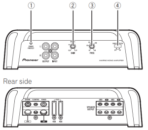

To adjust the switch, use a flathead screwdriver if needed
- POWER/PROTECT indicator
The power indicator lights up to indicate power ON.- If something is not normal, the indicator turns red.
- GAIN (gain) control
If the output remains low, even when the stereo volume is turned up, turn the controls to a lower level. If distortion occurs when the stereo volume is turned up, turn these controls to a higher level.- For use with an RCA equipped stereo (standard output of 500 mV), set to the NORMAL position. For use with an RCA equipped Pioneer stereo, with maximum output of 4 V or more, adjust level to match that of the stereo output.
- For use with an RCA equipped stereo with output of 4 V, set to the H position.
- If you hear too much noise when using the speaker input terminals, turn the gain control to higher level.
- LPF (low-pass filter) cut off frequency control
You can select a cut off frequency from 40 Hz to 240 Hz - SUBSONIC FILTER Switch
When turned ON, frequencies of 30 Hz and below are cut
Setting gain properly
- Protective function included to prevent malfunction of the unit and/or speakers due to excessive output, improper use or improper connection.
- When outputting high volume sound etc., this function cuts off the output for a few seconds as a normal function, but output is restored when the volume of the head unit is turned down.
- A cut in sound output may indicate impro-per setting of the gain control. To ensure continuous sound output with the head unit at a high volume, set amplifier gain control to a level appropriate for the preout maximum output level of the head unit, so that volume can remain unchanged and to control excess output.
- Despite correct volume and gain settings, the unit sound still cuts out periodically. In such cases, please contact the nearest authorized Pioneer Service Station.
Gain control of this unit

Above illustration shows NORMAL gain setting.
Relationship between amplifier gain and head unit output power

If amplifier gain is raised improperly, this will simply increase distortion, with little increase in power.
Signal waveform when outputting at high volume using amplifier gain control.

If the signal waveform is distorted due to high output, even if the amplifier gain is raised, the output power will change only slightly.
Connecting the Unit
Connection diagram

- Battery wire (sold separately)
- The maximum length of the wire between the fuse and the positive + terminal of the battery is 30 cm (12 in.).
- `For the wire size, refer to Connecting the power terminal. The battery wire, the ground wire and the optional direct ground wire must be same size. After making all other connections at the amplifier, connect the battery wire terminal of the amplifier to the positive + terminal of the battery.
- Fuse (80 A) (sold separately) Each amplifier must be separately fused at 80 A.
- Positive + terminal
- Negative (*) terminal
- Battery (sold separately)
- Ground wire, Terminal (sold separately) The ground wires must be same size as the battery wire.
- Stereo with RCA output jacks (sold separately)
- External output
- Connecting wire with RCA pin plugs (sold separately)
- Amplifier with RCA input jacks (sold separately)
- RCA input jack
- RCA output jack
- System remote control wire (sold separately)
- Speaker output terminals Please see the following section for speaker connection instructions. Refer to Connections when using the speaker input wire.
- Fuse (40 A) x 2
- Front side
- Rear side
Before connecting the amplifier
WARNING
- Secure the wiring with cable clamps or adhe-sive tape. To protect the wiring, wrap sections in contact with metal parts in adhesive tape.
- Never cut the insulation of the power supply to feed power to other equipment. Current ca-pacity of the wire is limited. A CAUTION
- To prevent water from entering the amplifier. attach a cover or cap to each terminal when not in use.
- Never shorten any wires, the protection circuit may malfunction.
- Never wire the speaker negative cable directly to ground.
- Never band together multiple speaker’s negative cables.
- If the system remote control wire of the amplifier is connected to the power terminal via the ignition switch (12V DC). the amplifier will re-main on with the ignition whether the stereo is on or off, which may exhaust battery if the engine is at rest or idling.
- Install and route the separately sold battery wire as far as possible from the speaker wires. Install and route the separately sold battery wire, ground wire, speaker wires and the amplifier as far away as possible from the antenna, antenna cable and tuner.
Connecting the speakers
This amplifier can be connected to two speakers in parallel. Connect the speaker leads to suit the mode according to the figure shown below.
Precautions for parallel connection
- When wiring two speakers in parallel, make sure that the synthetic impedance is from 1 Ω to 8 Ω to prevent the amplifier from catching fire, generating smoke and/or being damaged.
- When connected in parallel with the synthetic impedance less than 1 Ω , as a normal function, this amplifier may automatically be set on mute if outputting high volume sound. Turn down the volume until the mute function is canceled.
When connecting to one speaker

When connecting to two speakers
The output from two speakers is the same as that of one speaker.

Connections when using the speaker input wire
Connect the stereo speaker output wires to the amplifier using the supplied speaker input wire with RCA pin cord.

- Stereo
- Speaker output
- Red: Right +
- Black: Right *
- Black: Left *
- White: Left +
- Speaker input wire with RCA pin cord To the RCA input jack of this unit
Notes
- If speaker input wires from a headunit are connected to this amplifier, the amplifier will automatically turn on when the headunit is turned on. When the headunit is turned off, the amplifier turns off automatically. This function may not work with some headunits. In such cases, please use a system remote control wire (sold separately). If multiple amplifiers are to be connected together synchronously, connect the head unit and all amplifiers via the system remote control wire.
- This amplifier automatically selects an input signal mode between the RCA level and the speaker level by detecting an input signal
Solderless terminal connections
- Since the wire may become loose over time, it must be periodically inspected and tightened as necessary.
- Do not solder or bind the ends of the twisted wires.
- Fasten while making sure to not to clamp the insulating sheath of the wire.
- Use the supplied hexagonal wrench to tighten and loosen the terminal screw of the amplifier and use it to securely fasten the wire. Be careful to avoid excessive tightening of this screw, which may damage the wire.
Connecting the power terminal
WARNING
If the battery wire is not securely fixed to the terminal using the terminal screws, there is a risk of overheating, malfunction and injury, including minor burns.
- Always use the recommended battery and ground wire, which is sold separately. Connect the battery wire directly to the boat battery positive (+) terminal and the ground wire to the boat body.
- Recommended wires size (AWG: American Wire Gauge) is as follows. The battery wire, the ground wire and the optional direct ground wire must be same size.
- Use a wire of 12 AWG to 16 AWG wire for the speaker wire.
Route battery wire from engine compartment to the boat interior.
- When drilling a cable pass-thru into a bulk head or barrier wall, route the cable through carefully and seal the hole to prevent fumes from seeping from engine compartment to other areas. After completing all other amplifier connections, finally connect the battery wire terminal of the amplifier to the positive + battery terminal.

- Positive + terminal
- Battery wire (sold separately) The maximum length of the wire between the fuse and the positive + terminal of the battery is 30 cm (12 in.).
- Fuse (80 A) (sold separately) Each amplifier must be separately fused at 80 A
Use wire cutters or a utility knife to strip the end of the battery wire, ground wire and system remote control wire to expose about 10 mm (3/8 in.) of the end of each of the wires, and then twist the exposed ends of the wires.

Connect the wires to the terminal. Fix the wires securely with the terminal screws.

- Battery wire
- Power terminal
- Ground wire
- GND terminal
- System remote control wire
- System remote control terminal
- Terminal screws
Connecting the speaker output terminals
- Use wire cutters or a utility knife to strip the end of the speaker wires to expose about 10 mm (3/8 in.) of wire and then twist the wire.
- Connect the speaker wires to the speaker output terminals. Fix the wires securely with the terminal screws.


- Terminal screws
- Speaker wires
- Speaker output terminals
Before installing the amplifier
WARNING
- To ensure proper installation, use the supplied parts in the manner specified. If any parts other than those supplied are used, they may damage internal parts of the amplifier, or become loose causing the amplifier to shut down.
- Do not install in:
- Places where injury could occur if the boat stops suddenly.
- Places where it may interfere with the boat’s operator.
- Install tapping screws in such a way that the screw tip does not touch any wire. This is important to prevent wires from being cut by vibration of the boat, which can result in fire.
- Make sure that wires do not get caught in the sliding mechanism or touch the legs of a person in the boat as short-circuit may result.
- When drilling to install the amplifier, always confirm no parts are behind the panel and protect all cables and important equipment (e.g. cables, wiring, hoses, and modules) from damage.
CAUTION
- To ensure proper heat dissipation of the amplifier, ensure the following during installation:
- Allow adequate space above the amplifier for proper ventilation.
- Do not cover the amplifier.
- Place all cables away from hot places, such as near the heater outlet.
- The optimal installation location differs depending on the boat model. Secure the amplifier at a sufficiently rigid location.
- Check all connections and systems before final installation.
Installation
Example of installation on the chassis
- Place the amplifier in the desired installation location. Insert the supplied tapping screws (4 mm × 18 mm (5/32 in. × 3/4 in.)) into the screw holes and push on the screws with a screwdriver so they make an imprint where the installation holes are to be located.
- Drill 2.5 mm (3/32 in.) diameter holes in the chassis.
- Install the amplifier with the use of supplied tapping screws (4 mm × 18 mm (5/32 in. × 3/4 in.))
- Tapping-screws (4 mm × 18 mm (5/32 in. × 3/4 in.))
- Drill a 2.5 mm (3/32 in.) diameter hole
- Installation surface
- Hole-to-hole distance: 229.5 mm (9-1/32 in.)
- Hole-to-hole distance: 191.5 mm (7-17/32 in.)
- Attach the fuse cover and panel cover. Attach the panel cover to the amplifier using the supplied machine screws (3 mm × 10 mm (1/8 in. × 3/8 in.))


When installing the amplifier in a place that is prone to getting wet, install it to a wall with the power/speaker output terminals and RCA jacks on the left and right sides.

Additional information
Specifications
- Power source: 14.4 V DC (10.8 V to 15.1 V allowable)
- Grounding system: Negative type
- Current consumption: 22 A (at continuous power, 4 W)
- Average current consumption: 2.4 A (4 W for one channel)
3.6 A (2 W for one channel)
5.7 A (1 W for one channel) - Fuse: 40 A × 2
- Dimensions (W × H × D): 252 mm × 60 mm × 215 mm (9-7/8 in. × 2-3/8 in. × 8-1/2 in.)
- Weight: 2.7 kg (6 lbs) (Leads for wiring not included)
- Maximum power output: 600 W × 1 (4 W) / 1 600 W × 1 (1 W)
- Continuous power output: 300 W × 1 (at 14.4 V, 4 W,
20 Hz to 240 Hz, ≦ 1 % THD)
500 W × 1 (at 14.4 V, 2 W,
100 Hz, ≦ 1 % THD)
800 W × 1 (at 14.4 V, 1 W,
100 Hz, ≦ 1 % THD - Load impedance: 4 W (1 W to 8 W allowable)
- Frequency response: 10 Hz to 240 Hz (+0 dB, –3 dB)
- Signal-to-noise ratio: 100 dB (IHF-A network)
- Low pass filter: Cut off frequency: 40 Hz to 240 Hz
Cut off slope: –12 dB/oct - Subsonic filter: Cut off frequency: 30 Hz
Cut off slope: –24 dB/oct - Gain control:
RCA: 0.2 V to 6.5 V
Speaker: 0.8 V to 16 V - Maximum input level / impedance:
RCA: 6.5 V / 25 kW
Speaker: 16 V / 12 kW - Power output ……………………….. 300 W RMS × 1 Channel (at
14.4 V, 4 W, 20 Hz to 240 Hz and ≦ 1 % THD+N)
500 W RMS × 1 Channel (at
14.4 V, 2 W, 100 Hz and ≦ 1 % THD+N)
800 W RMS × 1 Channel (at
14.4 V, 1 W, 100 Hz and ≦ 1 % THD+N) - S/N ratio ………………………………… 75 dBA (reference: 1 W into 4 W)
CTA2006 Specifications

Accessories
- Panel cover × 1
- Fuse cover × 1
- Speaker input wire × 1
- Hexagonal wrench × 1
- Mounting screw (4 × 18 mm) × 4
- Mounting screw (3 × 10 mm) × 3
Notes
- Specifications and the design are subject to modifications without notice.
- The average current consumption is nearly the maximum current consumption by this unit when an audio signal is input. Use this value when working out total current consumption by multiple power amplifiers.