HP X27c 27 Inch Curved FHD 1ms 165Hz Gaming Monitor Owner’s Manual
hp X27c 27 Inch Curved FHD 1ms 165Hz Gaming Monitor Owner’s Manual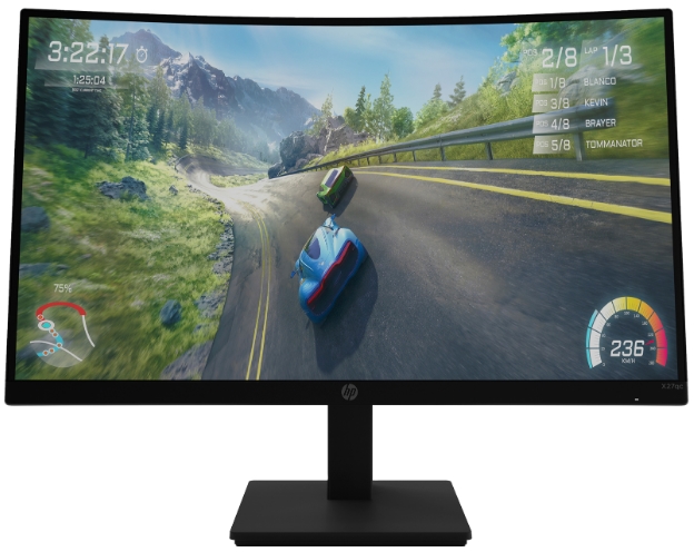

SUMMARY
This guide provides information about spare parts, removal and replacement of parts, diagnostic tests, problem troubleshooting, and more.
AMD is a trademark of Advanced Micro Devices, Inc. Bluetooth is a trademark
owned by its proprietor and used by HP Inc. under license. NVIDIA is a trademark
and/or registered trademark of NVIDIA Corporation in the U.S. and other countries. USB Type-C and USB-C are registered trademarks of USB Implementers Forum. DisplayPort and the DisplayPort logo are trademarks owned by the Video Electronics Standards Association (VESA) in the United States and other countries.
The information contained herein is subject to change without notice. The only warranties for HP products and services are set forth in the express warranty statements accompanying such products and services. Nothing herein should be construed as constituting an additional warranty. HP shall not be liable for technical or editorial errors or omissions contained herein.
- First Edition: March 2022
- Document Part Number: M45867-X27cMSG-V1
- Assembly part number: M45867-001
Product notice
Only trained service personnel familiar with this product should service it. Before
performing any maintenance or service, be sure to read “Important Safety Information”.
Getting started
Read this chapter to learn about safety information and where to find additional HP resources.
Important safety information
Carefully read the cautions and notes within this document to minimize the risk of personal injury to service personnel. The cautions and notes are not exhaustive. Proper service methods are important to the safe, reliable operation of equipment. Improper service methods can damage equipment.
The service procedures recommended and described in this service manual provide effective methods of performing service operations. Service engineers should have prior repair knowledge and experience as well as appropriate training for the product before performing service procedures.
- Be sure your working environment is dry and clean and meets all government safety requirements.
- Be sure that other persons are safe while you are servicing the product.
- Do not perform any action that can cause a hazard to the customer or make the product unsafe.
- Use proper safety devices to ensure your personal safety.
- Always use approved tools and test equipment for servicing.
- Never assume the product’s power is disconnected from the main power supply. Check that it is disconnected before opening the product’s cabinet.
- Modules containing electrical components are sensitive to electrostatic discharge (ESD).
Follow ESD safety procedures while handling these parts. - Some products contain more than one battery. Do not disassemble or expose a battery to high temperatures, such as throwing into fire, or the battery may explode.
- Refer to government requirements for battery recycling or disposal.
This information provides general service information for the monitor. Adherence to the procedures and precautions is essential for proper service.
IMPORTANT: Only trained service personnel who are familiar with this HP product should perform service or maintenance for it. Before performing any service or maintenance, personnel must read the important safety information.
IMPORTANT: You must disconnect the power cord from the power source before opening the monitor to prevent component damage.
Important service information and precautions
- Repair must be performed by professional service technicians in a repair center. End users should not perform these procedures.
- Please note during servicing that the primary side is the high voltage area.
- This monitor meets ROHS requirements. Be sure to use lead-free solder wire when soldering.
- If you must change a capacitor, be sure to match the polarity as printed on the PCB.
- If you must replace a capacitor, make sure the specification and part number match the BOM and location.
- If you must replace a capacitor, insert new parts carefully to avoid a short circuit caused by the near pin.
- Do not get the board wet. Water and moisture can cause a short circuit that causes malfunctions.
- To avoid damage, be sure to use lead-free solder.
- When soldering, work quickly to avoid overheating the circuit board.
- Keep the soldering iron tip clean and well tinned when replacing parts.
- After repair, perform a close inspection of the circuit board to confirm it is in good condition.
- After repair, perform a function test to confirm the power supply is working properly.
ERP Lot5 requirement
- A professional repairer must have the technical competence to repair electronic displays and comply with the applicable regulations for repairers of electrical equipment in the Member States where the repairer operates. Reference to an official registration system as professional repairer, where such a system exists in the Member States, shall be accepted as proof of compliance.
- A professional repairer must have insurance that covers liabilities resulting from repairs, regardless of whether required by the Member State.
RoHS (2002/95/EC) requirements
Applied to all countries that require RoHS.
The RoHS (Restriction of Hazardous Substance in Electrical and Electronic Equipment Directive) is a legal requirement by the EU (European Union) for the global electronics industry sold in the EU and other countries. Any electrical and electronics products launched in the market after June 2006 should meet this RoHS requirement. Products launched in the market before June 2006 are not required to be compliant with RoHS parts. If the original parts are not RoHS complaint, the replacement parts can be non-ROHS complaint. If the original parts are RoHS compliant, the replacement parts MUST be RoHS complaint.
If product service or maintenance requires replacing parts, confirm the RoHS requirement before replacement.
General descriptions
This manual contains general information. There are two levels of service:
- Level 1: Cosmetic/appearance/alignment service
- Level 2: Circuit board or standard parts replacement
Firmware updates
Firmware updates for the monitor are available at support.hp.com. If no firmware is posted, the monitor does not need a firmware update.
Before returning the repaired product to the customer
Perform an AC leakage current check on exposed metallic parts to be sure the product is safe to operate without the potential of electrical shock. Do not use a line isolation transformer during this check.
Measurements that are not within specified limits present a possible shock hazard. You must check and repair the product before returning it to the customer.
Monitor features
This chapter provides an overview of the monitor’s features.
Features
Depending on the model, your monitor might include the following features:
- 68,6 cm(27in) curved 1500mm radius with 2560×1440 resolution, ultra-wide backlit display, plus full-screen support for lower resolutions
- Antiglare panel with an LED backlight
- Wide viewing angle to allow viewing from a sitting or standing position, or moving from side to side
- Tilt adjustment capability
- Height adjustment capability
- DisplayPort (DP) video input
- High-Definition Multimedia Interface(HDMI) video input (cable provided)
- Audio-out (headphone)jack
- Plug and Play capability, if supported by your operating system
- Security cable slot provision onrear of monitor for optional security cable
- On-screen display (OSD) adjustments in several languages for easy setup and screen optimization
- High-bandwidth Digital Content Protection (HDCP) copy protection on all digital inputs
- VESA mounting bracket for attaching the monitor to a wall-mount device or swing arm
- Low blue light mode settings to create a more relaxing and less stimulating image
- Energy saver feature to meet requirements for reduced power consumption
NOTE: For safety and regulatory information, refer to the Product Notices provided in your documentation kit. To access the latest user guides or manuals for your product, go to http://www.hp.com/support and follow the instructions to find your product. Then select Manuals.
Front components
To identify the components on the front of the monitor, use this illustration and table.
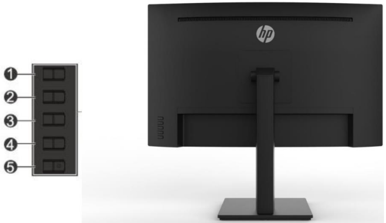

Table 1-1: Front components and their descriptions
| Component | Function | |
| 1 | Menu/OK | If the OSD menu is open, press to confirm selection. If the OSD menu is closed, press to open the OSD menu. |
| 2 | Next Active Input/Up/Increase button | If the OSD menu is close, switches the monitor’s input source to the next active input. If the OSD menu is close, press to open the information menu at HDMI, or to perform auto adjustment at VGA.* |
| 3 | Color Modes/Down/Decre ase button | If the OSD menu is close, opens the Color menu where you can adjust the monitor screen to a comfortable If the OSD menu is open, press to navigate forward through the OSD menu and decrease adjustment levels. |
| 4 | Brightness+ Input/Exit/Back button | If the OSD menu is close, opens the Brightness+ adjustment scale. If the OSD menu is closed, press to switch to the next video input port.* |
| 5 | Power button | Turns the monitor on or off. |
Rear components
To identify the components on the rear of the monitor, use this illustration and table.

Table 1-2: Rear components and their descriptions
| Component | Function | |
| 1 | Power connector | Connects the power cord |
| 2 | HDMI port | Connects an HDMI cable from the monitor to a source device such as a computer. |
| 3 | DisplayPort in connector | Connects the DisplayPort cable from the monitor to a source device such as a computer. |
| 4 | Headphone jack | Connect the headphone to the monitor. |
Locating the serial number and product number
he SPEC label is located on the rear of the monitor. The serial number and product number are located on a Safety label. You may need these numbers when contacting HP about the monitor model.

For worldwide models (except India):
Spec label

Illustrated parts catalog
To identify the monitor major components, use this illustration and table.

| Item | Description | Qty |
| 1 | DECO_BEZEL L27WR-Dblc1hp-p12 | 1 |
| 2 | LENS_POWER | 1 |
| 3 | PANEL | 1 |
| 4 | MIDDLE_FRAME L27WR-Dblc1hp-p12 | 1 |
| 5 | INSULATING SHEET 34.1*17 | 1 |
| 6 | POWER BOARD | 1 |
| 7 | MAIN BOARD | 1 |
| 8 | MAINFRAME | 1 |
| 9 | KEY BOARD | 1 |
| 10 | LED BOARD | 1 |
| 11 | REAR_COVER | 1 |
| 12 | stand ass’y NA NA | 1 |
| 13 | BASE_ASS’Y NA NA | 1 |
| S1 | 0M1G3030 4120 | 9 |
| S2 | 0D1G1030 6120 | 4 |
| S3 | QM1G38400601200ARA | 1 |
| S4 | 0D1G1030 6120 | 2 |
| S5 | 0M1G3030 4120 | 2 |
| S6 | 0Q1G 930 5120 | 1 |
| S7 | 0M1G2940 10 47 CR3 | 4 |
How to order parts
The HP authorized repair center can purchase the power board from HP.
Power board
| Description | HP spare part number | Manufacturer part number |
| PSU X27c 1st source | M84744-001 | PLPCKH362UQA1 |
| PSU X27c 2nd source | M84744-002 | PLPCKH362UQA2 |
Capacitors and connectors are available for purchase from the following EU distributors:
- Farnell: Farnell UK – Electronic Components Distributor
- RS Component: Capacitors | RS Components (rs-online.com)
- Digi-Key: Digikey Electronics
Capacitors by distributor
| Component description | Location | Component distributor | Distributor part number |
| EC 680uF 20% 35V 12.5*20 3000 hr 2A PY1V | C905/C906 | Digi-Key | EGPA350ELL681MK20S |
| EC 470uF 20% 25V 10×12 5000 hr 1.6A ENB1 | C9905 | RS | EEUFR1E471 |
Connectors by manufacturer
| Component description | Location identifier | Component distributor | Distributer part number |
| HDMI | CN501 | RS | SD-47151-001 (Molex) |
| DP | CN551 | Farnell | DP1RD20JQ3 (JAE) |
| AUDIO | CN601 | RS | 913-1021 (RS PRO) |
NOTE: Rear cover and chassis need to be modified to hold connector. Connector may need modifications to meet functional, safety and regulatory requirements accordingly if it doesn’t match exactly.
You can purchase cables from the HP part store at https://partsurfer.hp.com/Search.aspx.
Internal and External Power Supplies are available for purchase from the following EU distributor: EET https://www.eetgroup.com/en-eu/
NOTE: HP continually improves and changes product parts. For complete and current information about supported parts for your product, go to https://partsurfer.hp.com/Search.aspx, select your country or region, and then follow the on-screen instructions.
Removal and replacement procedures
Adherence to these procedures and precautions is essential for proper service.
Preparation for disassembly
Use this information to properly prepare to disassemble and reassemble the monitor.
- Read the “Important safety information” and “Important service information and precautions” sections in the “Getting started” chapter of this guide.
- Clean the room for disassembly.
- Identify the disassembly area.
- Check the position that the monitors are to be placed along with the number of monitors. Prepare the area for material flow according to the disassembly layout.
- Be sure to have the following equipment and materials:
- Press fixture
- Working table
- Screwdriver
- Knife
- Gloves
- Cleaning cloth
- ESD protection
- Scraper bar in the following dimensions:

Rear Cover
Before removing the Rear Cover, follow these steps:
Prepare the monitor for disassembly. See Preparation for disassembly.
Remove the Rear Cover:
- Remove four screw from the rear case.
- Use your fingers to split the left and right sides apart between the middle frame and rear case.
- Insert the scraper bar tool into the gap between the middle frame and rear case, and then rotate. The hook opens. Repeat the steps.
- Disassemble Rear Cover.
- Remove the key board wire from the Interface-board.
- Disassemble the Key board and LED board from the Rear Cover (if required).
- Tear off the tapes.
- Remove 2 screws from the main frame.
- Remove 2 screws from bracket
- Disassemble 5 screws from the board.
- Disassemble all the boards from housing.
- Disconnect all the wires from the board.


Power board
The power board part number is PLPCKH362UQA1 (1st source) or PLPCKH362UQA2 (2nd source).
Before removing the power board, follow these steps:
Prepare the monitor for disassembly. See Preparation for disassembly .
Remove the power board:
- The HP X27c power board connector position is as follows:
- Locate the part number location on the board


Connector repair
This procedure includes HDMI, DisplayPort and Audio connectors.
The connectors are on the main board (board part number CBPC1A8HPQ1)
The connectors’ identifiers are as follows:
| Connector | Location |
| HDMI | CN501 |
| DisplayPort 1 | CN551 |
| Audio | CN601 |

Before repairing connectors, follow these steps:
Prepare the monitor for disassembly. See Preparation for disassembly .
IMPORTANT
- Repair Condition: Connector repair is only for out of warranty.
- Repairing must operate by professional repairers (Note) in repair center, not applicable for end user.
- Electrostatic protection is required when component replacement is required.
- The monitor meets ROHS, please use Lead-free solder wire for soldering.
- If Connector need to replace, must check specification and part number whether match the BOM and location.
- If connector need to replace, please insert new parts carefully because the near pin may cause short circuit by inappropriate operate.
- DO NOT allow any liquid on the board. Water and moisture may cause short-circuit to the electronic components and lead to malfunctions.
- The fusion point of Lead-Free solder is requested. Repairing with conventional lead wire may cause damage.
- Work quickly to avoid overheating the circuit board as soon as you confirm the steady soldering condition.
- Keep the soldering iron tip clean and well tinned and when replacing parts.
- A close inspection of the circuit board revealed look in good condition.
- After repaired, must connect source to each port to check Main board function is ordinary.
Note: (The requirement of professional repairers’ regulation by ERP lot5)
- The professional repairer has the technical competence to repair electronic displays and complies with the applicable regulations for repairers of electrical equipment in the Member States where it operates. Reference to an official registration system as professional repairer, where such system exists in the Member States concerned, shall be accepted as proof of compliance with this point.
- The professional repairer is covered by insurance covering liabilities resulting from its activity, regardless of whether this is required by the Member State.
HDMI connector CN501
Repair the HDMI connector:
- Use a soldering iron and a de-soldering pump to remove as much solder as possible from the pin.
- Use a hot air gun to melt the solder on the pins.
- Lift the CN501 connector from the circuit board.
- Place the new component on the circuit board. Be sure that it matches the footprint.
- Solder the new component.


DP connector CN551
Repair the DP connector:
- Use a soldering iron and a de-soldering pump to remove as much solder as possible from the pin.
- Use a hot air gun to melt the solder on the pins.
- Lift the CN551 connector from the circuit board.
- Place the new component on the circuit board. Be sure that it matches the footprint.
- Solder the new component.


Audio Connector CN601
Repair the DP connector:
- Use a soldering iron and a de-soldering pump to remove as much solder as possible from the pin.
- Use a hot air gun to melt the solder on the pins.
- Lift the CN601 connector from the circuit board.
- Place the new component on the circuit board. Be sure that it matches the footprint.
- Solder the new component.

Function test
After repair, be sure to confirm that all functions are working.
Table 4-1: Function test
| Test item | Operating description | Tool used |
| HDMI test | Confirm whether image displays and sound plays correctly on the monitor. | Computer or DVD player |
| DP test | Confirm whether image displays and sound plays correctly on the monitor. | Computer or DVD player |
| Audio test | Change volume and balance to confirm whether volume is smooth and loud enough. | Speaker |
Support and troubleshooting
The following table lists possible problems, the possible cause or each problem, and the recommended solutions.
Table 4-2: Solving common problems
| Problem | Possible cause | Solution |
| Screen is blank or video is flashing. | Power cord is disconnected. | Connect the power cord. |
| Monitor is off. | Power the power button. NOTE: If pressing the Power button has no effect, press and hold the power button for 10 seconds to disable the Power button lockout feature. | |
| Video cable is improperly connected. | Connect the video cable properly. | |
| System is in Auto-Sleep Mode. | Press any key on the keyboard or move the mouse to inactivate the screen blanking utility. | |
| Video card is incompatible. | Open the OSD menu and select the Input menu. Set Auto-Switch Input to Off and manually select the input or replace the video card or connect the video cable to one of the computer’s on-board video sources. | |
| Image appears | Brightness is too low. | Open the OSD menu and |
| blurred, indistinct, or too dark. | select Brightness to adjust the brightness scale as needed. | |
| Check Video Cable is displayed on screen. | Monitor video cable is disconnected. | Connect the appropriate video signal cable between the computer and monitor. Be sure that the computer power is off while you connect the video cable. |
| Input Signal Out of Range is displayed on screen. | Video resolution and/or refresh rate are set higher than what the monitor supports. | Change the settings to a supported setting. |
| The monitor does not enter into a low-power sleep state. | The monitor’s power saving control is disabled. | Open the OSD menu and select Power, select Auto- Sleep Mode, and then set auto-sleep to On. |
| “OSD Lockout” is displayed | The monitor’s OSD lock function is enabled. | Press and hold the Menu button for 10 seconds to disable the OSD Lockout function. |
| Power Button is Locked is Displayed | The monitor’s Power Button Lockout function is enabled. | Press and hold the Power button for 10 seconds to unlock the power button function. |