Honeywell MILLER Beam Trolley & Painters Trolley User Manual


 |


Miller Beam Trolley & Painter’s Trolley
User Instruction Manual Manuel D’utilisation / Manual de Instrucciones para El Usuario
Thank You
Thank you for your purchase of Miller Fall Protection equipment. Miller brand products are produced to meet the highest standards of quality at our ISO 9001 certified facility. Miller Fall Protection equipment will provide you with years of use when cared for properly.

Questions?|
It is crucial that the authorized person/user of this fall protection equipment read and understand these instructions. In addition, it is the employer’s responsibility to ensure that all users are trained in the proper use, inspection, and maintenance of fall protection equipment. Fall protection training should be an integral part of a comprehensive safety program.
Proper use of fall arrest systems can save lives and reduce the potential of serious injuries from a fall. The user must be aware that forces experienced during the arrest of a fall or prolonged suspension may cause bodily injury. Consult a physician if there is any question about the user’s ability to use this product. Pregnant women and minors must not use this product.
Purpose and Specifications
The Miller Beam Trolley (9065) is designed to provide a single user with an easily installed anchorage connector on horizontal I-beams. The beam trolley is adjustable and slides along with the worker to provide maximum safety and mobility.
Model No. |
Description | Fits Flange Sizes | Materials | Weight | Tensile Strength |
| 9065 | Adjustable beam trolley for installation to horizontal I-beams |
3″ (76.2mm) to 4-1/2″ (114.3mm) wide 5HWURfiW KiWV DOORZ EHDP WUROOH\ WR DFFRPPRGDWH DQ H[WHQGHG UDQJH RI EHDP flDQJH Vi]HV: 9065-1 – 3″ (76.2mm) to 8-1/2″ (215.9mm) wide 9065-2 – 3″ (76.2mm) to 12″ (304.8mm) wide |
Steel | 17 lbs (7.7kg) | 5,000 lbs (22.2kN) minimum |
The Miller Painter’s Trolley (9059-1) is designed to provide a single user with an easily installed anchorage connector on 1-1/2 inch (38mm) diameter steel rail/rods, such as those used around the exterior of a water tower. The trolley slides along with the worker and automatically bypasses intermediate supporting rods to provide continuous fall protection.
Model No. |
Description | Fits Rail/Rod Sizes | Materials | Weight | Tensile Strength |
| 9059-1 | Painter’s trolley for install- location to horizontal steel rail/rods | 1-1/2″ (38mm) diameter | Stainless Steel | 6.6 lbs (3kg) | 5,000 lbs (22.2kN) minimum |
General Requirements, Warnings, and Limitations
All warnings and instructions shall be provided to authorized persons/users.
All authorized persons/users must reference the regulations governing occupational safety, as well as applicable ANSI or CSA standards. Please refer to the product labeling for information on specific OSHA regulations, and ANSI and CSA standards met by the product.
Proper precautions should always be taken to remove any obstructions, debris, material, or other recognized hazards from the work area that could cause injuries or interfere with the operation of the system.
All equipment must be inspected before each use according to the manufacturer’s instructions.
All equipment should be inspected by a qualified person on a regular basis.
To minimize the potential for accidental disengagement, a competent person must ensure system compatibility.
Equipment must not be altered in any way. Repairs must be performed only by the manufacturer, or persons or entities authorized in writing by the manufacturer.
Any product exhibiting deformities, unusual wear, or deterioration must be immediately discarded.
Any equipment subject to a fall must be removed from service.
The authorized person/user shall have a rescue plan and the means at hand to implement it when using this equipment.
Never use fall protection equipment for purposes other than those for which it was designed. Fall protection equipment should never be used for towing or hoisting.
Equipment must not be exposed to environmental hazards and chemicals which may produce a harmful effect.
Use in a corrosive or caustic environment dictates a more frequent inspection and servicing program to ensure the integrity of the product is maintained.
Do not allow equipment to come in contact with anything that will damage it including, but not limited to, sharp, abrasive, rough, or high-temperature surfaces, welding, heat sources, electrical hazards, or moving machinery.
Do not expose the equipment to any hazard which it is not designed to withstand. Consult the manufacturer in cases of doubt.
Always check for obstructions below the work area to make sure the potential fall path is clear.
Allow adequate fall clearance below the work surface.
The purchaser of this equipment must ensure that all personnel using this equipment are familiar with these instructions and are properly trained in the operation, limitations, installation, inspection, and maintenance of this product. Training should be conducted periodically and without exposing the trainee to a fall hazard.
Never remove product labels, which include important warnings and information for the authorized person/user.
Installation & Use
Warnings and Limitations
Before installation of any anchorage connector, carefully inspect to ensure that it is in useable condition. Check for missing or damaged parts. Do not use this equipment if any component does not operate properly or if the unit appears to be damaged in any way. Refer to the inspection section of this manual.
Miller Trolleys are designed for use with Miller-approved components. Substitution or replacement with non-approved component combinations or subsystems or both may affect or interfere with the safe function of each other and endanger the compatibility within the system. This incompatibility may affect the reliability and safety of the total system.
Fall arrest systems used with the anchorage connector must be rigged in accordance with regulatory requirements. [All instructions and warnings provided with the components of the personal fall arrest system must be read, understood, and followed.]
Make sure that all connections within the fall arrest system are compatible.
Use only locking carabiners, locking snap hooks, or other Miller-approved connectors or connecting devices to attach to this equipment.
The anchorage connector must be compatible with the snap hook or carabiner of the connecting device and must not be capable of causing a load to be applied to the gate/ keeper. Never use an anchorage connector that will not allow a snap hook or carabiner gate/keeper to close.
Anchor and system must be installed and used in such a manner as to minimize the potential for a swing fall hazard and limit free fall distance to 6 feet (1.8m) or less.
Ensure that the anchorage connector is at a height that will not allow a lower level to be struck should a fall occur. When selecting an anchorage point, always remember that shock absorbers will elongate when subjected to fall arrest forces. Refer to the labels and instructions provided with the connecting device to obtain the maximum elongation distance.
The structure that this product is attached to must be capable of supporting 5,000 lbs. (22.2kN) per user attached; or be designed, installed, and used, under the supervision of a safety factor of at least two.
Anchorage requirements based on ANSI are as follows:
- For fall arrest systems, anchorages must withstand a static load of 5,000 lbs. (22.2kN) for non-certified anchorages or two times the maximum arresting force for certified anchorages.
- When more than one personal fall arrest system is attached to an anchorage, the above anchorage strengths must be multiplied by the number of personal fall arrest systems attached to the anchorage.
The Miller 9065 Beam Trolley and the Miller 9059-1 Painter’s Trolley meet OSHA and ANSI A10.32 & Z359.1*.
[Note: If the system is used by an employee having a combined tool and body weight between 310 lbs. (140.6 kg) and 400 lbs. (181.4 kg), then the employer must appropriately modify the criteria and protocols to provide proper protection for such heavier weights, or the system will not be deemed to be in compliance with the requirements of OSHA 1926.502(d)(16).] *ANSI Z359.1 capacity range is 130 lbs. (59kg) to 310 lbs. (140.6kg).
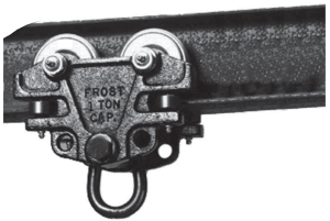
9065 Beam Trolley
Installation Requirements
- Beam must be capable of supporting a 5,000 lb. (22kN) static load in the direction permitted by the system while in use (or provide a 2:1 safety factor). This requirement must be met at all points along the length of the beam to which the trolley may travel.
- The device shall be connected such that it will not slide off the end of a beam (end stops must be used to limit trolley travel) and should not be attached to a beam that is inclined or sloped. This device must only be used on beams where a fall will not cause the device to slide along the beam and increase the fall distance.
- Use only on straight, horizontal, overhead I-beams with no obstructions, modifications, or cutouts in the bottom flange of the beam.
Beam Trolley

Installation
- Select an approved mounting location (beam) that meets or exceeds all installation requirements. Measure the width of the beam flange.
- Assemble trolley prior to installation to determine proper configuration of the spacer washers. Move spacer washers from the inside of the trolley side flanges (see locations A & B of Fig. 1) to the outside of the flanges (see locations C & D of Fig. 1) or vice versa until the distance between the side rollers is 1/8″ (3mm) larger than the beam flange width with the adjustment bolt tight.
Note: There should always be at least one washer at each of the four locations–A, B, C, and D. The number of washers at locations A & B should be equal or differ by only one washer. It is important not to remove any of the spacer washers. Move excess spacer washers to locations C and/or D. This will ensure proper alignment between the cotter pin hole and adjustment nut as shown in Figures 1 and 2. - Once the proper location for the spacer washers has been determined, remove the assembly nut, spacer washers at location D, and the trolley side flange between locations D & A. Lift the trolley into position on the beam flange and slide the loose trolley side flange back into position on the assembly bolt. Replace the spacer washers and assembly nuts. Hand tightens the assembly bolt and nut.
- Ensure that the attachment ring is in a down position as shown in Figure 1. Pull straight down on the ring to ensure that all four trolley wheels are in contact with the beam flange.
- Verify that there is no more than 1/8″ (3mm) of clearance between the sides of the beam flanges, and the adjacent side rollers. If more than 1/8″ clearance is present, remove the trolley and adjust the spacer washers accordingly.
- lighten the attachment bolt and nut to approximately 30-40 ft. lbs.
- Insert the cotter pin provided into the hole at the end of the attachment bolt and through the cut-outs in the attachment nut. (Note: It may be necessary to tighten the attachment nut slightly to align the cutouts in it with the cotter pin hole in the attachment bolt.) Bend the ends of the cotter pin as shown in Figure 1 to prevent disengagement.
8. Apply grease to each of the grease fittings (8 total). (See Greasing in 4.0 Inspection & Maintenance.)
Beam Trolley with Retrofit Kit

Use Warnings and Limitations
- Inspect before each use (see 4.0 Inspection & Maintenance).
- For use by ONE person only. The maximum capacity is 400 lbs. (181.4kg), including body weight, clothing, and tools. — DO NOT EXCEED
THIS WEIGHT
- The trolley must be directly above the worker to avoid swing falls. Sideloading is not per-missable as it may damage the trolley and cause an accident.
- Use only with a Miller-approved shock-absorbing lanyard or self-retracting lifeline/fall limiter.
- Connect to the attachment ring only with a locking snap hook, locking carabiner, or another Miller-approved connector. Always visually check that the snap hook/carabiner gate is completely closed and locked when in use.
9059-1 Painter’s Trolley
Installation Requirements
- Steel rail/rod must be capable of supporting a 5,000 lb. (22kN) static load in the direction permitted by the system while in use (or provide a 2:1 safety factor). This requirement must be met at all points along the length of the rail to which the trolley may travel.
- Rail/rod must be 1-1/2 inches (38mm) in diameter. Use only on the horizontal, overhead rail.
- The device shall be connected such that it will not slide off the end of the rail (rail must be a closed path or end stops must be used to limit trolley travel) and should not be attached to rail which is inclined or sloped. This device must only be used on the rail where a fall will not cause the device to slide along the rail and increase the fall distance.
Painter′s Trolley

Installation
- Select an approved mounting location (rail/rod) that meets or exceeds all installation requirements.
- Open the spring-loaded gate on the trolley (see Fig. 4a) and install it onto the rail/rod as shown in Figure 4b.
- Once installed, make sure that the trolley gate is not obstructed and is in a closed position.
Important: Trolley gate must be closed (see Fig. 3 & 4b) during use to prevent trolley from disengaging from rail if inadvertently turned sideways or upside down. Because the trolley gate is spring-loaded, it is designed to automatically bypass supporting rods for continuous fall protection along the length of the rail.

Use Warnings and Limitations
- Inspect before each use (see 4.0 Inspection & Maintenance).
- For use by ONE person only. The maximum capacity is 400 lbs. (181.4kg), including body weight, clothing, and tools. — DO NOT EXCEED
THIS WEIGHT.
- The trolley must be directly above the worker to avoid swing falls.
- Connect to the attachment ring only with a locking snap hook, locking carabiner, or another Miller-approved connector. Always visually check that the snap hook/carabiner gate is completely closed and locked when in use.
- While in use, do not remove the trolley at any point along the length of the rail. It is designed to automatically bypass supporting rods.
Inspection and Maintenance
Inspection
Miller Trolleys are designed for today’s rugged work environments. To maintain their service life and high performance, devices should be inspected frequently. These devices must be visually inspected by the user before each use and inspected by a Competent Person on a regular basis, at least annually.
Inspect product for any of the following: bent, cracked, distorted, worn, malfunctioning or damaged parts; loose fasteners or missing parts/components; deterioration; deformation; corrosion; signs that indicate the product has been subjected to a fall arrest; or any other indications of damage/problems that may affect the integrity and operation of the product. If in doubt, contact the manufacturer.
- Check the trolley to be sure that it operates freely.
- Inspect assembly nuts and ensure that they are tightened to required specifications.
- A Cotter pin on the beam trolley must be present and properly installed to prevent disengagement.
- The spring-loaded gate on the painter’s trolley must open and close properly. Spring must exert sufficient force to maintain the gate in the closed position. Ensure that paint build-up does not interfere with the proper operation of the trolley gate (see Cleaning and Storage).
Devices that do not pass inspection or have been subjected to fall arresting forces must be removed from service.
Greasing (9065 Trolley only)
Grease for the 9065 Trolley should be general-purpose bearing grease unless site conditions deem otherwise (high/low temperature, food-grade, etc).
Greasing frequency depends on usage. Refer to the guidelines below.
9065 Beam Trolley Greasing Criteria |
Grease once a year | Grease once every 6 months | Grease once every 3 months | Grease once
per month |
| Low/infrequent usage in a clean, room temperature environment | ||||
| Low/infrequent usage in a high contamination/heat/exterior environment | ||||
| Medium usage (several times per week with high travel distances) in a clean, room temperature environment | ||||
| High Usage (daily with high travel distances) in a clean, room temperature environment | ||||
| High Usage in a high contami- nation/heat/exterior environ- ment |

NOTE: If in doubt about the greasing requirements, please contact the manufacturer.
Note about the bearings – The side rollers have less grease retention capability but are also not load-bearing. The main bearings are shielded against contamination and have good grease retention, but are not totally sealed. If deemed necessary, due to fear of contamination from the environment, both of these bearings can be purged to remove old grease.
Cleaning and Storage
Basic care of all Miller Fall Protection equipment will prolong the life of the unit and will contribute toward the performance of its vital safety function. Periodically clean the device to remove any dirt, paint, corrosives, contaminants, or other materials that may have accumulated. Wipe off all surface dirt with a sponge dampened in plain water or a mild solution of water and commercial soap or detergent. Then wipe dry with a clean cloth. Hang or blow the unit off with compressed air to dry. When not in use, store in a clean, dry area, free of exposure to fumes or corrosive elements.
Servicing
Servicing of Miller Fall Protection equipment must only be carried out by Miller Fall Protection or persons or entities authorized in writing by Miller Fall Protection. A record log of all servicing and inspection dates for this device must be maintained. Only original Miller replacement parts are approved for use in this device. Non-repairable devices that do not pass an inspection must be disposed of in a manner to prevent inadvertent further use. Contact Miller Technical Services at 800.873.5242 if you have any questions.
Product Labels
MILLER by Honeywell
9065 TROLLEY Honeywell Safety Products Franklin, PA 16323 1-800-873-5242
CAPACITY: 1 WORKER (400 POUNDS MAX.)
MATERIAL: STEEL
COMPLIANCE: ANSI A10.14 & Z359.1, OSHA 1926.502
REFER TO INSTRUCTIONS SUPPLIED WITH EQUIPMENT AT TIME OF SHIPMENT FOR INSTALLATION AND INSPECTION REQUIREMENTS
YEAR OF MANUFACTURE:
MILLER by HoneywellWARNING
– USER MUST READ, UNDERSTAND, & FOLLOW MANUFACTURERS INSTRUCTIONS SUPPLIED WITH EQUIPMENT AT THE TIME OF SHIPMENT
– USE ONLY FOR PERSONNEL, NOT FOR SUPPORT
– USE ONLY WITH APPROVED SHOCK-ABSORBING LANYARD OR DECELERATING TYPE RETRACTABLE LIFELINE.
– DO NOT USE IF CLEARANCE BETWEEN I-BEAM FLANGE AND WHEEL FLANGE, ON BOTH SIDES, COLLECTIVELY EXCEEDS 3/16″.
– BEAM MUST BE ABLE TO SUPPORT A MINIMUM OF 5,000 LBS. AT CENTER OF SPAN.
– INSPECT FREQUENTLY, TIGHTEN ADJUSTING NUTS TO 30-40 LT-LBS. AND INSTALL COTTER PINS BEFORE USE. DO NOT USE IF THE UNIT APPEARS TO BE DAMAGED OR MALFUNCTIONING.
– SUPPORT BEAMS MUST-HAVE STOPS IN PLACE PRIOR TO TROLLEY USE.
– TROLLEY MUST BE POSITIONED DIRECTLY ABOVE THE WORKER TO AVOID SWING FALLS. – 400 LB. RATED CAPACITY MUST NOT BE EXCEEDED.

9059-1 Painter’s Trolley
Honeywell Safety Products Material: Stainless Steel Franklin, PA 16323 Capacity: 1-800-873-5242 OSHA – 1 worker (400lbs. MAX) ANSI- 1 worker (130 lbs. – 310 lbs.) Year of Manufacture: 2012
Compliance ANSI A10.32 OSHA 1926.502 ANSI Z359.1
WARNING
- User must read, understand, & follow manufacturers’ instructions supplied with equipment at the time of shipment
- Use only locking carabiners or other Miller-approved connectors to attach to this equipment.
- Use only on 1-1/2″ diameter steel rods capable of supporting 5,000 lbs. The trolley must be positioned directly above the worker to avoid swing falls.
- Do not use if the unit appears damaged or malfunctioning.
- Refer to instructions for proper installation of the trolley.
- Use only for personnel, not for support.
- Inspect before each use.
LB1199 Rev. B|
Inspection and Maintenance Log
| DATE OF MANUFACTURE: | |
| MODEL NUMBER: | |
| DATE PURCHASED: |
| INSPECTION DATE | INSPECTION ITEMS NOTED | CORRECTIVE ACTION | MAINTENANCE PERFORMED |
| Approved by: | |||
| Approved by: | |||
| Approved by: | |||
| Approved by: | |||
| Approved by: | |||
| Approved by: : | |||
| Approved by: | |||
| Approved by: | |||
| Approved by: | |||
| Approved by: |

Toll Free:800.873.5242
Fax:800.892.4078
Download this manual at: www.millerfallprotection.com
Honeywell Safety Products P.O Box 271, 1345 15th Street Franklin, PA 16323 USA