Dell S2721D 27-Inch QHD Monitor User Guide
DELL S2721DB
1. Disassembly Procedures
S1 Turn off the monitor.
S2 Place the monitor on a soft cloth or cushion.
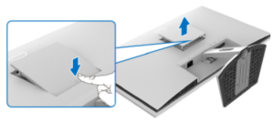
Press the dimple on the VESA cover to release it from the back of the display.

S3 Using a long screwdriver, push the release latch located in the gap just above the stand.

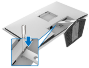
S4 Once the latch is released, slide the stand assembly away from the monitor

S5
Unlock 2 Stand screws
Unlock 4 screws on Rear Cover
(Screw Torque: RC screw: 8.5±1.0kgf Stand screw: 4~5kgf)

S6 Follow the sequence to disassemble Rear Cover from the monitor

S7 Tear off all adhesive tapes from backlight wire and SPK wire

S8
Unlock 6 SPK screws
Pull out SPK wire from I/F BD
Disassemble SPK from Middle Frame
(Screw Torque: 4~6kgf)

S9 Tear off AL Tape Pull out CTRL FFC from I/F BD Pull out backlight wire from SPS and Panel
(Screw Torque: 6~7kgf)


S10 Unlock 6 “ASSY DECO” screws
(Screw Torque: 1.5~2.5kgf)

S11 Unlock 11 MF screws
(Screw Torque: 4~5kgf)

S12 Unlock 4 Main SHD screws
(Screw Torque: 6~7kgf)

S13 Pull out FFC LVDS from the Panel
Take off Main SHD from Panel
Disassemble Middle Frame and “ASSY DECO” from the panel

S14
Unlock 2 screws on CTRL BD
(Screw Torque: 1.5~2.5kgf)


S16 Disassemble CTRL BD FFC from CTRL BD

S17 Disassemble CTRL BD from OSD BTN

S18 Disassemble Safety Mylar from SPS BD
S19 Disassemble the little Mylar from Main SHD


S20
Unlock 8 PCBA screws Disassemble I/F BD & SPS BD from Main SHD
(Screw Torque: 6~7kgf)

S21 Pull out FFC eDP from the I/F BD

S22 Remove electrolyte capacitors (red mark) from printed circuit boards

S22-1 Cut the glue between bulk caps. and PCB with a knife

S22-2 Ensure cutting path within the glue, don’t touch bulk cap. or PCB

S22-3 Take out the bulk cap. pin solder with soldering iron and absorber

S22-4 Lift the bulk cap. up and away from the PCB

2. Product material information
The following substances, preparations, or components should be disposed of or recovered separately from other WEEE in compliance with Article 4 of EU Council Directive 75/442/EEC.
| Capacitors / condensers (containing PCB/PCT) | No used |
| Mercury-containing components | No used |
| Batteries | No used |
| Printed circuit boards (with a surface greater than 10 square cm) | The product has printed circuit boards (with a surface greater than 10 square cm) |
| The component contains toner, ink, and liquids | No used |
| Plastic containing BFR | No used |
| Component and waste contain asbestos | No used |
| CRT | No used |
| Component contain CFC, HCFC, HFC and HC | No used |
| Gas discharge lamps | No used |
| LCD display > 100 cm2 | The product has an LCD greater than 100 cm2 |
| External electric cable | The product has external cables |
| The component contains refractory ceramic fibers | No used |
| The component contains radioactive substances | No used |
| Electrolyte capacitors (height > 25mm, diameter > 25mm) | Product has electrolyte capacitors (height > 25mm, diameter > 25mm) |
3. Tools Required
List the type and size of the tools that would typically be used to disassemble the product to a point where components and materials requiring selective treatment can be removed.
Tool Description:
- Screwdriver
- Scraper Bar
- Penknife
- Soldering iron and absorber