Asus PN50 Mini Desktop PC User Guide


ASUS PN50 Mini Desktop PC

Package Contents
- ASUS Mini PC PN Series
- AC Power Adapter
- Power Cord
- Technical Documentations


Features
NOTE: The port and/or icon may be covered up for items labeled with on selected models if the item is unavailable for your model.
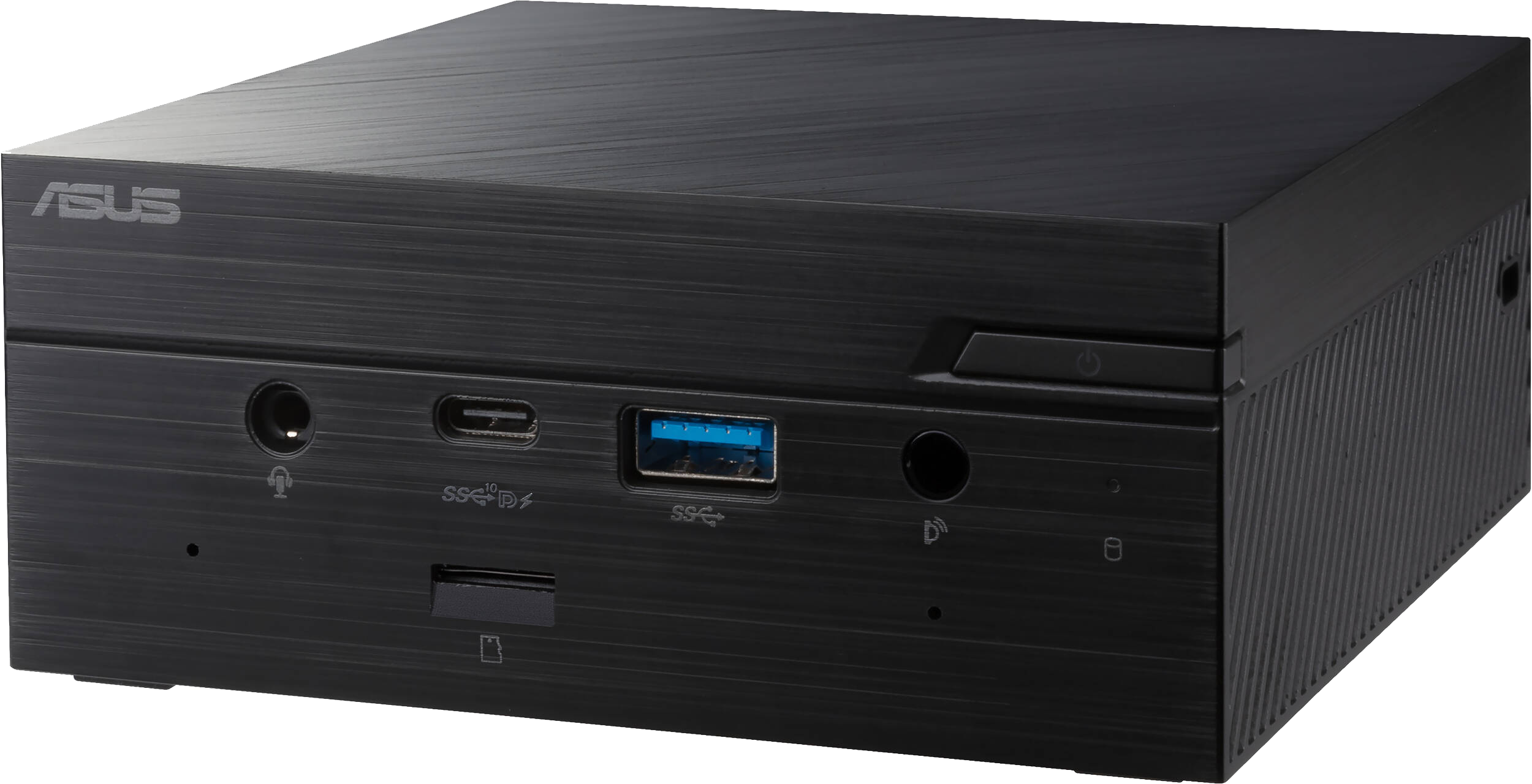
Front View

- Power Button
The power button allows you to turn the Mini PC on or off. You can use the power button to put your Mini PC to sleep mode or press it for four (4) seconds to force shutdown your Mini PC. - Microphone (on Selected Models)
The built-in microphone can be used for video conferencing, voice narrations, or simple audio recording. - Headphone/Headset/Microphone Jack (on Selected Models)
This port allows you to connect amplified speakers or headphones. You can also use this port to connect your headset or an external microphone. - USB 3.2 Gen 2 Type-C®/DisplayPort combo Port
This USB Type-C® (Universal Serial Bus) port provides a transfer rate of up to 10 Gbit/s, and supports Display port 1.4. Use a USB Type-C® adapter to connect your Mini PC to an external display. This port also supports the Battery Charging 1.2 technology that allows you to charge your USB devices.
NOTE:- Battery Charging 1.2 technology is only available on selected models, and provides a maximum of 5V / 1.5A output.
- When using only this port as a display output source, this port will support a resolution of up to 7680 x 4320 @30Hz, or 5120 x 2280 @120Hz. The resolution may also be affected by the cabling and output device.
- Memory Card Slot (on selected models)
The built-in memory card reader enables your Mini PC to read and write data to and from Micro SD cards. - USB 3.2 Gen 1 Port
The USB 3.2 Gen 1 (Universal Serial Bus) port provides a transfer rate up to 5 Gbit/s. - IR Receiver (on Selected Models)
The remote sensor detects signal from your remote control, allowing you to access the control panel from a distance.
NOTE: The remote control is purchased separately. - Drive Activity Indicator
This indicator lights up when your Mini PC is accessing the internal storage drive.
Left View

- Air Vents (Intake Vent)
The air vents allow cooler air to enter your Mini PC chassis.
IMPORTANT: For an optimum heat dissipation and air ventilation, ensure that the air vents are free from obstructions.
Right View

- Air Vents (Intake Vent)
The air vents allow cooler air to enter your Mini PC chassis. - Kensington® Security Slot
The Kensington® security slot allows you to secure your Mini PC using Kensington® security products. - HDMI™ Port
The HDMI™ (High Definition Multimedia Interface) port supports a Full-HD device such as an LCD TV or monitor to allow viewing on a larger external display.
NOTE: When using only this port as a display output source, this port will support a resolution of up to 3840 x 2160 @60Hz. The resolution may also be affected by the cabling and output device. - Air Vents (Exhaust Vent)
The air vents allow your Mini PC chassis to expel hot air out.
IMPORTANT: For an optimum heat dissipation and air ventilation, ensure that the air vents are free from obstructions. - Configurable Port
This port varies between models and consists of the following port options:- VGA Port
This port allows you to connect your Mini PC to an external display.
NOTE: When using only this port as a display output source, this port will support a resolution of up to 1920 x 1200 @60Hz. The resolution may also be affected by the cabling and output device. - Serial (COM) Connector
The 9-pin serial (COM) connector allows you to connect devices that have serial ports such as mouse, modem, or printers. - LAN Port
The 8-pin RJ-45 LAN port supports a standard Ethernet cable for connection to a local network. - DisplayPort
This port allows you to connect your Mini PC to an external display.
NOTE: When using only this port as a display output source, this port will support a resolution of up to 4096 x 2160 @60Hz. The resolution may also be affected by the cabling and output device.
- VGA Port
- USB 3.2 Gen 2 Type-C®/DisplayPort Combo Port
This USB Type-C® (Universal Serial Bus) port provides a transfer rate of up to 10 Gbit/s, and supports Display port 1.4. Use a USB Type-C® adapter to connect your Mini PC to an external display.
NOTE: When using only this port as a display output source, this port will support a resolution of up to 7680 x 4320 @30Hz, or 5120 x 2280 @120Hz. The resolution may also be affected by the cabling and output device. - LAN Port
The 8-pin RJ-45 LAN port supports a standard Ethernet cable for 10/100/1000/2500Mbps connection to a local network. - USB 3.2 Gen 1 ort
The USB 3.2 Gen 1 (Universal Serial Bus) port provides a transfer rate up to 5 Gbit/s. - Power Input
The supplied power adapter converts AC power to DC power for use with this jack. Power supplied through this jack supplies power to the Mini PC. To prevent damage to the Mini PC, always use the supplied power adapter.
WARNING! The power adapter may become warm to hot when in use. Do not cover the adapter and keep it away from your body.
NOTE: The power adapter rating may vary between models, please refer to the following information on the power adapter:
65W Power adapter: +19.0V DC = 3.42A, or +19.5V DC = 3.33A, 65.0W
90W Power adapter: +19.0V DC = 4.74A, or +19.5V DC = 4.62A, 90.0W
Getting Started
- Connect the Power Adapter and Cord
- Connect a display panel to your Mini PC by connecting a display cable either to the VGA port, HDMI™ port, DisplayPort, or one of the USB 3.2 Gen 2 Type-C®/DisplayPort combo port.
- Up to four display panels may be connected simultaneously when using both front and rear USB 3.2 Gen 2 Type-C®/DisplayPort combo ports, HDMI™ port, and configurable port*.
- Using a one of the ports listed below as the only display output source will provide the following maximum resolution**:
- Front USB 3.2 Gen 2 Type-C®/DisplayPort combo port
Supports a resolution of up to 7680 x 4320 @30Hz, or 5120 x 2280 @120Hz. - Rear USB 3.2 Gen 2 Type-C®/DisplayPort combo port
Supports a resolution of up to 7680 x 4320 @30Hz, or 5120 x 2280 @120Hz. - HDMI™ port
Supports a resolution of up to 3840 x 2160 @60Hz. - Configurable VGA port
Supports a resolution of up to 1920 x 1200 @60Hz. - Configurable DisplayPort port
Supports a resolution of up to 4096 x 2160 @60Hz.
* This port may vary per model. Please refer to the Features section for the location of the ports.
** The maximum resolution may be affected by the cabling and output device.
- Front USB 3.2 Gen 2 Type-C®/DisplayPort combo port
- Connect the wired or wireless keyboard and mouse
- Turn on your system


Upgrading your Mini PC
IMPORTANT!
- It is recommended that you install or upgrade the memory modules, wireless card, and solid state drive (SSD), under professional supervision. Visit an ASUS service center for further assistance.
- Ensure that your hands are dry before proceeding with the rest of the installation process. Before installing any of the features in this guide, use a grounded wrist strap or touch a safely grounded object or metal object to avoid damaging them due to static electricity.
NOTE: The illustrations in this section are for reference only. The slots may vary depending on model.
Removing the Bottom Cover
- Turn off your Mini PC then disconnect all cables and peripherals.
- Place the Mini PC on a flat stable surface, with its top side facing down.
- Remove the four (4) screws from the bottom (A), then push the bottom cover towards the right to remove the bottom cover (B).

Replacing the Bottom Cover
Push the bottom cover from the left side towards the right side of the Mini PC (A), then secure it using the four (4) screws removed previously (B).

Installing Memory Modules
Your Mini PC comes with two SO-DIMM memory slots that allow you to install two DDR4 SO-DIMMs.
IMPORTANT! Refer to http://www.asus.com for the list of compatible DIMMs. You can only install DDR4 SO-DIMMs to the Mini PC’s DIMM slots.
Align and insert the memory module into the slot (A) and press it down (B) until it is securely seated in place. Repeat the same steps to install the other memory module.

Installing 2.5″ HDD or SSD
- Prepare your 2.5″ HDD or SSD, then align it with the storage bay on the bottom cover of your Mini PC.
- Insert your HDD or SSD into the storage bay (A), then secure it with four (4) screws (B).
IMPORTANT! This device only supports 7mm and 9.5mm 2.5″ HDD or SSD.

Installing the M.2 SSD (on Selected Models)
- Align and insert the 2280 M.2 SSD into its slot inside the Mini PC.
- Gently push down the 2280 M.2 SSD on top of the screw hole and fasten it using one of the bundled 3mm round screws.

Installing the Wireless Card
NOTE: Your Mini PC includes a M.2 slot for 2230 wireless and Bluetooth modules. Refer to http://www. asus.com for the list of compatible wireless and Bluetooth modules.
- (Optional) Remove the M.2 SSD if an M.2 SSD is installed. To remove the M.2 SSD, remove the screw from the screw hole, then remove the M.2 SSD.
- Remove the M.2 stand screw.
- Align and insert the wireless card into its slot inside the Mini PC, then gently push down the wireless card on top of the screw hole and fasten it using the previously removed stand screw.
- (Optional) Connect the antennas to your wireless card.

NOTE:
- Connecting antennas to your wireless card may strengthen the wireless signal.
- A soft clicking sound indicates that the antenna has been securely attached on the wireless card.
Responsible Party: Asus Computer International
Address: 48720 Kato Rd, Fremont, CA 94538
Phone/Fax No: (510)739-3777/(510)608-4555
hereby declares that the product
Product Name: Desktop PC
Model Number: PN50, PN51
compliance statement:
This device complies with part 15 of the FCC Rules. Operation is subject to the following two conditions: (1) This device may not cause harmful interference, and (2) this device must accept any interference received, including interference that may cause undesired operation.