Honeywell 50061061 Arc Smart Position Sensor Instruction Manual
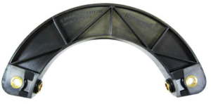
Honeywell 50061061 Arc Smart Position Sensor

GENERAL INFORMATION
Why is the SMART Position Sensor smart? SMART means that this is a sensor that can essentially think for itself. The SMART Position Sensor has the ability to self-calibrate because it uses a patented combination of an ASIC (Application-Specific Integrated Circuit) and an array of MR (magnetoresistive) sensors to accurately and reliably determine the position of a magnet attached to a moving object (e.g., elevator, valve, machinery, etc.) so that the object’s position can be determined.
The MR array measures the output of the MR sensors mounted along the magnet’s direction of travel. The output and the MR sensor sequence determine the nearest pair of MR sensors to the center of the magnet location. The output of these two MR sensors is then used to determine the position of the magnet between them. With this sensor, Honeywell has utilized MR technology through the ASIC at a level never before accomplished.
MOUNTING AND WIRING INFORMATION
(See Fig. 1.)
- Locate sensor and magnet in desired position. Ensure that the air gap between sensor and magnet does not exceed that noted in Table 1.
- Mount sensor:
● Drill two holes, one for each mounting ear.
● Secure sensor using two ¼-20 or M6 screws through each mounting ear.
● Torque screws to 6 N m to 8 N m [53.1 in lb to 70.8 in lb]. - Mount magnet:
● Drill two holes:
– One for the single mounting ear.
– One at 10,25 ±0.10 mm [0.403 ±0.004 in] dia., and at least 3 mm [0.118 in] deep, for the mounting dog (helps stabilize magnet).
● While ensuring the mounting dog is seated in its hole, secure magnet using one ¼-20 or M6 screw through the mounting ear.
● Torque screws to 6 N m to 8 N m [53.1 in lb to 70.8 in lb]. - Wire sensor according to pinout in Figure 2.
Table 1. Specifications
| Characteristic | Component |
Parameter | |||||
100 ° Arc |
180 ° Arc | ||||||
SPS-A100D- HAMS |
SPS-A100D- VAMS | SPS-A100D- HAWS | SPS-A100X- LAAS0401 | SPS-A180D- HAMS | SPS-A180D- VAMS | ||
| Sensing range | sensor only |
0° to 100° |
0° to 180° | ||||
| Sensing location on arc | inside | outside | inside | ||||
| Resolution | 0.06° |
0.11° | |||||
| Supply voltage | 6 Vdc to 24 Vdc |
18 Vdc to 40 Vdc | 6 Vdc to 24 Vdc | 5 Vdc | 6 Vdc to 24 Vdc | 18 Vdc to 40 Vdc | |
| Output | 0.5 Vdc to 4.5 Vdc (10% to 90% of 5 Vdc) | ||||||
| Supply current | 45 mA max. |
30 mA max. | 45 mA max. | ||||
| Linearity | ±0.4% full scale output | ||||||
| Reverse polarity | 26.4 Vdc |
40 Vdc | 26.4 Vdc | – | 26.4 Vdc | 40 Vdc | |
| Sensitivity | 40 mV/° ±4% FS |
22.22 mV/° ±4% FS | |||||
| Measurement frequency | 312 Hz typ. | ||||||
| Termination | 4-pin M12 connector |
18 AWG flying leads | Ampseal 16 connector (p/n 776536) |
4-pin M12 connector | |||
| Operating temperature | sensor and magnet actuator |
-40 °C to 85 °C [-40 °F to 185 °F] | |||||
| Storage temperature | -40 °C to 150 °C [-40 °F to 302 °F] | ||||||
| Air gap | 7,8 ±2,5 mm |
9,2 ±2,5 mm [0.36 ±0.09 in] |
8,58 ±2,5 mm | ||||
| Sealing | IP67, IP69K | ||||||
| Shock | 50 G half sine wave with 11 ms duration | ||||||
| Vibration | 20 G from 10 Hz to 2000 Hz | ||||||
| Housing material | thermoplastic | ||||||
| Approvals | CE | ||||||
| Mounting: screws recommended torque | M6 or 1/4-20 | ||||||
| Material | magnet actuator only |
neodymium | |||||
| Strength | 10,000 Gauss | ||||||
Notes:
- Tolerance applies for full sense range.
- Device used to read analog output must have input impedance greater than 1 MOhm.
- The output voltage outside of the valid measurement range will be indeterminate.
- Percent linearity is the quotient of the measured output deviation from the best fit line at the measured temperature to the full scale output span.
- Mating connector: 776536-1.
| NOTICE Ferrous metal within a 100 mm [3.9 in] radius of the magnet may affect sensor performance. |
Figure 1. Dimensional Drawings (For reference only: mm/in.)
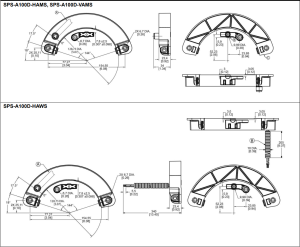
A = Cable direction for right angle connector
B = Polyethylene conduit

Figure 1. Dimensional Drawings (For reference only: mm/in.)
A = Magnet pin locating hole
B = Partial view
C = Rotating axis center
D = Magnetic sensitive zone: protect with a non-ferrous metal shield

Figure 1. Dimensional Drawings (For reference only: mm/in.)
A = Cable direction for right angle connector
B = Polyethylene conduit

Figure 2. Connection

Figure 3. Sensor Output Performance Chart Showing Ideal Outputs (Applies to all catalog listings.)

| PERSONAL INJURY
DO NOT USE these products as safety or emergency stop devices or in any other application where failure of the product could result in personal injury. Failure to comply with these instructions could result in death or serious injury. |

WARRANTY/REMEDY
Honeywell warrants goods of its manufacture as being free of defective materials and faulty workmanship. Honeywell’s standard product warranty applies unless agreed to otherwise by Honeywell in writing; please refer to your order acknowledgement or consult your local sales office for specific warranty details. If warranted goods are returned to Honeywell during the period of coverage, Honeywell will repair or replace, at its option, without charge those items it finds defective. The foregoing is buyer’s sole remedy and is in lieu of all other warranties, expressed or implied, including those of merchantability and fitness for a particular purpose. In no event shall Honeywell be liable for consequential, special, or indirect damages.
While we provide application assistance personally, through our literature and the Honeywell web site, it is up to the customer to determine the suitability of the product in the application.
Specifications may change without notice. The information we supply is believed to be accurate and reliable as of this printing.
However, we assume no responsibility for its use.
SALES AND SERVICE
Honeywell serves its customers through a worldwide network of sales offices, representatives and distributors. For application assistance, current specifications, pricing or name of the nearest Authorized Distributor, contact your local sales office or
E-mail:
Internet: sensing.honeywell.com
Phone and Fax:
Asia Pacific
+65 6355-2828
+65 6445-3033 Fax
Europe
+44 (0) 1698 481481
+44 (0) 1698 481676 Fax
Latin America
+1-305-805-8188
+1-305-883-8257 Fax
USA/Canada
+1-800-537-6945
+1-815-235-6847
+1-815-235-6545 Fax
Sensing and ControlHoneywell
1985 Douglas Drive North Golden Valley, MN 55422
sensing.honeywell.com
50061061-4-ML
February 2013

Copyright © 2013 Honeywell International Inc.
All rights reserved.