Honeywell S688A Sail Switch Installation Guide


Honeywell S688A Sail Switch
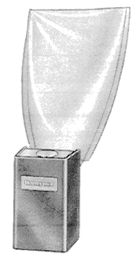

The Sail Switch activates an electronic air cleaner, a humidifier, or other equipment in response to air flow from the system fan. The S688A is mounted in the return air duct where the sail will be in the direct path of an unrestricted air stream.
- Simplified installations with multispeed fans, inaccessible air handlers, fan motors with voltage or phase different from controlled equipment; eliminated wiring to system fan.
- Polyester film sail mounted on a micro switch snap switch.
- Removable spring counterbalances sail to allow mounting in either vertical (up or down) or horizontal air flow.
- Top and bottom conduit knockouts for wiring convenience.
- Low air velocity switch operation-makes at 250 fpm and breaks at 75 fpm.
Specifications
MODEL: S688A Sail Switch.
ELECIRICAL RATINGS (Amperes):

SWITCIIlNG ACTION: Spdt snap-acting switch.
SAILDATA:
- Insertion length-IO in. [254 mm].
- Maximum width-5 in. [127 mm].
- Approximate area-26.2 in. 2(1690 mm2).
- Material-polyester film sealed on music wire frame.
MINIMUM AIR FLOW:
- N.O. Contacts: Makes-250 fpm.
- Breaks-75 fpm.
- N.C. Contacts: Makes-75 fpm.
- Breaks-250 fpm.
MAXIMUM AMBIENT 1EMPERATURES:
125° F [52° CJ at switches.
170° F [77° CJ at sail.
CASE DIMENSIONS:
2-5/16 in. [59 mm] high, 3-3/4 in.
[95 mm] wide, 2-1/8 in. [54 mm] deep.
DUCT MOUNTING HOLE DIMENSIONS:
1-1/2 in . [38 mm] by 2-1/4 in. [57 mm].
MOUNTING MEANS: Switch mounts on return air duct with two sheet metal screws. An adhesive backed mounting template is provided. Sail is inserted into duct through 1-1/2 in. [38 mm] by 2-1/4 in. [57 mm] hole.
MOUNTING POSITION: Mounts in vertical (up or down) or horizontal air flow.
WIRING KNOCKOUTS: 1/2 in. conduit knockout in either end of case.
FINISH: Zinc plated case and cover.
REPLACEMENT PARTS: Part no. 123773AReplacement Sail.
UNDERWRl1ERS’ LABORATORIES, INCL LIS1ED:
File No. E4436, Guide No. XAPX. For use in ambient temperatures normally prevailing in occupiable spaces, which usually are not higher than 77° F [25° C] but occasionally may be as high as 104° F [40° C] for brief periods.
Installation
CAUTION: Disconnect power supply before beginning installation to prevent electrical shock or equipment damage.
LOCATION: Locate the sail switch in the return air duct where the sail will be in the direct path of an unrestricted air stream. Maximum ambient temperature at the switch is 125° F [52° C] and at the sail is 170° F [77° CJ. The air duct at the
WHEN INSTALLING THIS PRODUCT …
- Read these instructions carefully. Failure to follow them could damage the product or cause a hazardous condition.
- Check the ratings given in the instructions and on the product to make sure the product is suitable for your application.
- Installer must be a trained, experienced service technician.
- After installation is complete, check out product operation as provided in these instructions.
Ordering Information
When purchasing replacement and modernization products from your TRADELINE® wholesaler or your distributor, refer to the TRADELINE Catalog or price sheets for complete ordering number, or specify-
- Order number, TRADELINE, if desired.
If you have additional questions, need further information, or would like to comment on our products or services, please write or phone:- Your local Honeywell Residential Sales Office (check white pages of phone directory).
- Residential Division Customer Satisfaction
Honeywell Inc., 1885 Douglas Drive North Minneapolis, Minnesota55422-4386 (612) 542-7500 In Canada-Honeywell Limited/Honeywell Limitee, 740 Ellesmere Road, Scarborough. Ontario MlP 2V9. International Sales and Service Offices in all principal cities of the world. Manufacturing in Australia, Canada, Finland, France, Germany, Japan, Mexico, Netherlands, Spain. Taiwan, United Kingdom, U.S.A.
Fig. 1–Mount sail switch in one of positions shown for elbow turning vanes or sweep radius Is recommended.

Fig. 2–Mount sail switch on center line of duct In one of angle-t positions shown for junction duct work.

Fig. 3-Mount sail switch In one of positions shown for angle-t junction duct work. Transition in trunk Is recommended.

must be at least 12in. [305 mm] deepand8 in. [203 mm] wide to allow operation of the sail without affecting the smooth flow of air in the duel Airflow at the location may be vertical (up or down) or horizontal.
Note: When S688 is mounted in warm air, the sail life may be reduced. Refer to Figs. 1-3 for the best duct mounting location. Mount the switch at least 6 in. [152 mm] upstream from an
elbow or junction, and at least 15 in. [381 mm] downstream from an elbow or junction. The switch must be located on the opposite side of the duct from the air entrance.
ADAPT SWITCH TO AIR FLOW DIRECTION
The S688A Sail Switch is provided with two counterbalancing springs in place as shown in Fig. 4. These springs offset the effect of gravity for air flow direction.
IMPORT
ANT: Never use the sail switch with both springs attached.
Fig. 4-Adapting sail switch to air flow direction.

Adapt the sail switch to mounting position. (FS2 requires special instructions; see separate instructions.)
Standard Application
Horizontal air flow-remove both springs. Vertical upward air flow-leave in place the spring that is attached to the bracket marked up. Remove the spring that is attached to the bracket marked down. Vertical downward air flow-leave in place the spring that is attached to the bracket marked down. Remove the spring that is attached to the bracket marked up.
F52 Application
Ceiling-remove both springs.
All other positions-leave in place the spring that is attached to the bracket marlced up. Renwve the spring that is attached to the bracket marked down.
Fig. 5-Adaptlng sail switch to F52 mounting position.

MOUNT THE SWITCH (See special instructions for F52)
The sail switch counterbalancing springs are calibrated for proper operation when the sail switch case is mounted at true level for horizontal air flow applications, or plumb for vertical air flow applications. Proceed as follows, using the mounting template provided.
- Mount the template at desired location. BE SURE THAT THE ARROW INDICATING AIRFLOW POINTS IN THE PROPER DIRECTION. Level the long dimension shown on the template for horizontal mounting. Plumb this dimension for vertical mounting.
- Cut the hole indicated on the template in the ductwork.
- Center punch the screw holes indicated and drill out with a 1/8 inch drill.
Fig. 6-Attaching sail to switch - Attach the sail to the switch as shown in Fig. 6.
NOTE: The sail switch makes at about 250 fpm and breaks at 75 fpm. In an average residential system that produces 500 fpm in the return air duct, the switch will make at approximately 50% and break at 15% of the maximum air flow rate. In a system where air flow may be as high as 1000 fpm the switch will not break until the air flow drops to about 7.5% of maximum. To retain the original on-off ratios of air flow, trim the sail. Trim about 1-1/2 in. [38 mm] from the sail for 1000 fpm air velocity and proportionally more or less for higher or lower velocity. Correct trimming is important If sail is too long, it will flutter and the wire frame may break prematurely; if it is too short, the switch may not operate. - Press the sides of the wire loop together. Insert the sail into the duct
- Before fastening the switch in position, check to make certain air movement will operate the switch. In the off position, the sail should point into the direction of airflow as shown inFig. 7.
Fig. 7-Posltion sail so it points Into the direction of airflow when switch is off. - Secure the switch by using the sheet metal screws provided. After wiring, snap on the cover. The Honeywell trademark tab can be snapped out and rotated 180 degrees so it will be upright for any vertical mounting position.


MOUNT SAIL SWITCH ON THE F52
- Remove the sail switch, L-shaped mounting bracket and smallparts envelopefrom theaircleaner wiring compartment
- Remove sail switch cover and remove knockout opposite of the arrow stamped on the inside of the case .
- Turn the air cleaner over and rest it on the carton.
- Mount the sail on the sail switch.
- Locate the two black wires extending from the back of the power supply. Pull wires through L-shaped bracket and case knockout Using two t.apered sheetmetal screws from the envelope, mount the L-shaped bracket to the air cleaner. Next, remove the ground screw on the sail switch to prevent interference with theL-shaped bracket Mount the sail switch to the L-shaped bracket with two 8-32 screws. Airflow should be in opposite direction of airflow arrow.
NO’IE: Although it is not recommended, if the two-cell air cleaner must be mounted horizontally with the power supply on the bottom, the sail switch must be installed at a 45 degree angle from vertical, see Fig. 8.
Fig. 8-Mount sail switch on back of power supply.
NOTE: IF AIR CLEANER IS MOUNTED HORIZONTALLY WITH THE POWER SUPPLY ON BOTTOM, THE SAIL SWITCH MUST BE MOUNTED AT A 45 DEGREE ANGLE FROM VERTICAL. - Mak:ewiring connectionstotheN.C.(normallyclosed) and COM (common) screw terminals in the sail switch.
- Replace sail switch cover.

WIRING & CAUTION
ELECTRIC SHOCK HAZARD. CAN CAUSE ELECTRICAL SHOCK OR EQUIPMENT DAMAGE.
Disconnect power supply before wiring. All wiring must comply with local electrical codes and ordinances. When controlling more than one device, make certain that the total electrical load does not exceed the switch rating (see Specifications). Typical wiring hookups that have the switching action at the sail switch are shown in Fig. 9. Normally open and normally closed refer to the contacts when the switch is in the de-energized position.
Fig. 9-Typical wiring hookups using sail switch to energize electronic air cleaner.

- POWER SUPPLY- PROVIDE OVERLOAD PROTECTION AND DISCONNECT MEANS AS REQUIRED.
- TERMINAL DESIGNATIONS ARE FOR POWER OFF: N.O. – NORMALLY OPEN, N.C. – NORMALLY CLOSED, COM.- COMMON.
Operation and Checkout
The sail switch has a spdt switch, which permits different hookups for controlling auxiliary equipment in a heatingcooling system. The hookups in Figs. 9 and 10, show systems where the controlled equipment operates only when the system fan operates. When the fan produces 250 fpm air velocity, the normally open contacts make, turning on the auxiliary equipment When the air velocity decreases to 75 fpm, the normally open contacts break, turning off the auxiliary equipment The hookup in Fig. 10 shows a system where auxiliary equipment operates when the system fan is off. Whenthefan produces250fpm air velocity, the normally closed contacts break, turning off the auxiliary equipment When the air velocity decreases to 75 fpm, the normally closed contacts make, turning on the auxiliary equipment.
CHECKOUT
When installation is complete, operate equipment through one complete cycle to make sure sail switch functions as described in OPERATION section.
Fig.10-Typical wiring hookups using sail switch to energize two-wire auxiliary equipment.

- POWER SUPPLY· PROVIDE OVERLOAD PROTECTION AND DISCONNECT MEANS AS REQUIRED.
- WHEN CONTROLLING EQUIPMENT WITH TWO LEADWIRES, WIRE SWITCH IN HOT (BLACK) LINE.
- TERMINAL DESIGNATIONS ARE FOR POWER OFF: N.O. -NORMALLY OPEN, N.C. • NORMALLY CLOSED, COM.- COMMON.