Honeywell R8285E Control Center Installation Guide
Honeywell R8285E Control Center Installation Guide
This is a legacy product document supported by Resideo. It is no longer manufactured
Application
R8285E Control Center provides low voltage control of line voltage fan motors and auxiliary circuits in heating, cooling, or air-conditioning systems.
REPLACEMENT RELAY: R8222F
SWITCHING: dpst; 1 N.0./1 N.C.
INPUT VOLTAGE: 120 Vac
CONTACT LOAD RATINGS: 12 AFL, 60 ALR at 120 Vac
The R8285E has dpst switching for two-speed fan motor and limit controller applications.
RELAY COIL RATINGS:
Inrush: 20 VA maximum.
Sealed: 9 VA.
Wattage: 5 watts.
Pickup voltage: Must pick up below 18 volts.
TRANSFORMER RATINGS:
Power rating: 40 VA
Primary voltage: 120 Vac.
Open circuit secondary voltage: 27.0.
Overload protection: Inherent.
Frequency: 60 Hz.
Installation
WHEN INSTALLING THIS PRODUCT…
- Read these instructions carefully. Failure to follow them could damage the product or cause a hazardous condition.
- Check the ratings given in these instructions and on the product to ensure the product is suitable for your application.
- Ensure installer is a trained, experienced service technician.
- After completing installation, use these instructions to check product operation.


Disconnect power supply before beginning installation to prevent electrical shock and equipment damage.
MOUNTING
The R8285 mounts on a standard four inch square junction box. Make wiring connections in the junction box, then fasten the R8285 to the junction box by placing the junction box screws through the notches in the R8285 mounting plate.
NOTE: The R8285 must be mounted in an enclosure. The R8285 may be mounted in any position except with the mounting plate horizontal and the relay on top of the mounting plate.
WIRING
All wiring must comply with local codes and ordinances. Disconnect power before making wiring connections to prevent electrical shock or equipment damage.
- Make primary connections to line voltage power supply.
- Make secondary connections to 24 Vac control circuit.
- Refer 1o Fig. 1 for typical wiring diagram.
IMPORTANT: Only use Underwriters Laboratories Inc. listed connectors when making external circuit connections to the line voltage leadwires of this device.
Fig. 1 — R8285E typical hookup in two-speed fan and limit controller application.
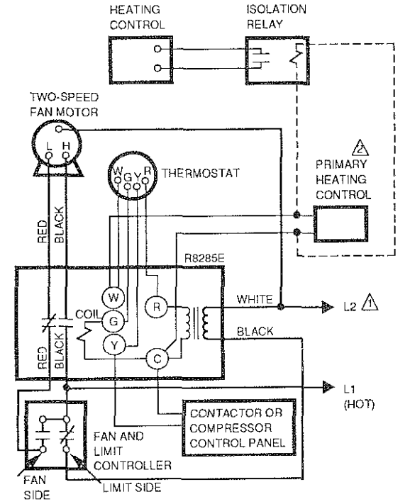


Power supply. Provide disconnect means and overload protection as required.
Use optional hookup with isolating relay (dashed line) if heating control has a separate power supply. Isolation of the power supplies may also be accomplished by using special thermostat subbase combinations with isolated circuits (such as T87F-Q539A1147, T834A, T822A). Refer to specification sheets for details.
Checkout
Always conduct a thorough checkout when installation is complete. Operate the system through at least one complete cycle to ensure that the system equipment and the R8285 operate as intended.
Service
Disconnect the power supply before servicing to prevent electrical shock and equipment damage.
The R8285 relay is field replaceable. Replace the relay as follows:
- Remove the plug-in relay from the receptacle and replace with the R8222F relay. Refer to Fig. 2.
Fig. 2 — Mounting relay to R8285E Relay Receptacle.


Helping You Control Your World

Residential and Building Controls Division
Honeywell Inc.
1985 Douglas Drive North
Golden Valley, Minnesota 55422
Residential and Building Controls Division
Honeywell Limited–Honeywell Limitée
740 Ellesmere Road
Scarborough, Ontario
MIP2V9