Makita 2107F Portable Band Saw Instruction Manual


makita 2107F Portable Band Saw
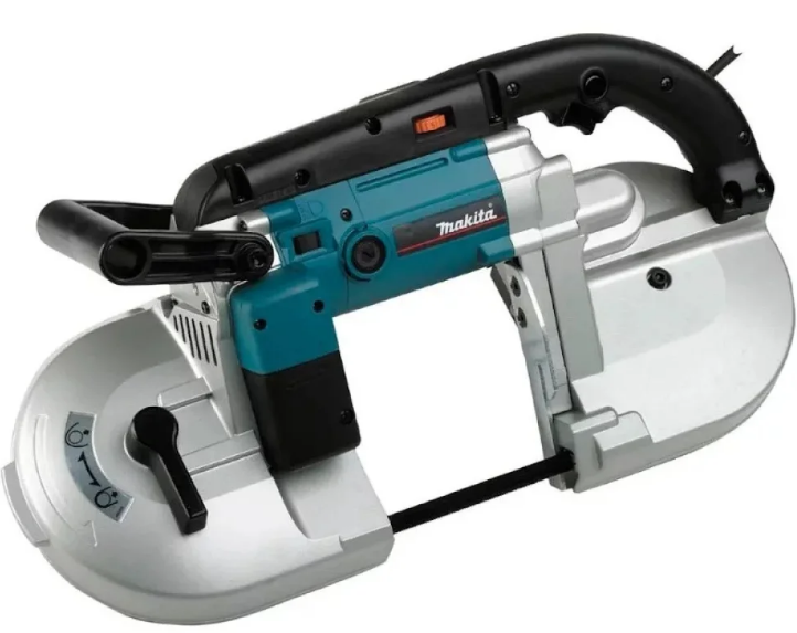

Explanation of general view
- Lock button
- Switch trigger
- Speed adjusting dial
- Lamp switch
- Tighten
- Loosen
- Protrusion
- Lever
- Blade
- Bearing
- Upper holder
- Lower holder
- Upper holder
- Lower holder
- Wheel
- Press
- Screw
- Stopper plate
- Blade
- Cutting wax
- Wheel
- Tire
- Lip
- Fluorescent tube
- lump box
- Tapping screw
- Limit mark
- Screwdriver
- Brush holder cap
SPECIFICATIONS
| Model | 2107F | |
|
Max. cutting capacity |
Round workpiece | 120 mm dia. |
| Rectangular workpiece | 120 mm x 120 mm | |
| Blade speed | 1.0 – 1.7 m/s | |
|
Blade size |
Length | 1,140 mm |
| Width | 13 mm | |
| Thickness | 0.5 mm | |
| Overall dimensions | H x W x L | 496 mm x 184 mm x 249 mm |
| Net weight | 6.0 kg | |
| Safety class | /II | |
- Due to our continuing programme of research and development, the specifications herein are subject to change without notice.
- Specifications may differ from country to country.
- Weight according to EPTA-Procedure 01/2003
Intended use
The tool is intended for cutting in wood, plastic and ferrous materials.
Power supply
The tool should be connected only to a power supply of the same voltage as indicated on the nameplate, and can only be operated on single-phase AC supply. They are double-insulated in accordance with European
Standard and can, therefore, also be used from sockets without earth wire.
Noise
The typical A-weighted noise level determined according to EN60745:
Sound pressure level (LpA) : 86 dB(A)
Sound power level (LWA) : 98 dB(A)
Uncertainty (K) : 3 dB(A)
Wear ear protection
Vibration
The vibration total value (tri-axial vector sum) determined according to EN60745:
Work mode : cuttig chipbord
Vibration emission (ah,CW) : 2.5 m/s2 or less
Uncertainty (K) : 1.5 m/s2
Work mode: cutting metal
Vibration emission (ah,CM) : 2.5 m/s2 or less
Uncertainty (K) : 1.5 m/s2
For European countries only
EC Declaration of Conformity
We Makita Corporation as the responsible manufacturer declare that the following Makita machine(s):
Designation of Machine:
Portable Band Saw
Model No./ Type: 2107F are of series production and
Conforms to the following European Directives:
98/37/EC until 28th December 2009 and then with 2006/42/EC from 29th December 2009
And are manufactured in accordance with the following standards or standardised documents:
The technical documentation is kept by our authorised representative in Europe who is:
Makita International Europe Ltd,
Michigan, Drive, Tongwell,
Milton Keynes, MK15 8JD, England
30th January 2009
Tomoyasu Kato
Director
Makita Corporation
3-11-8, Sumiyoshi-cho,
Anjo, Aichi, JAPAN
General Power Tool Safety
Warnings
WARNING Read all safety warnings and all instructions. Failure to follow the warnings and instructions may result in electric shock, fire and/or serious injury.
Save all warnings and instructions for future reference.
PORTABLE BAND SAW SAFETY
WARNINGS
- Hold power tool by insulated gripping surfaces, when performing an operation where the cutting accessory may contact hidden wiring or its own cord. Cutting accessories contacting a “live” wire may make exposed metal parts of the power tool “live” and could give the operator an electric shock.
- Use only blades which are 1,140 mm (44-7/8″)long, 13 mm (1/2″) wide, and 0.5 mm (.020″) thick.
- Check the blade carefully for cracks or damage before operation. Replace cracked or damaged blade immediately.
- Secure the workpiece firmly. When cutting a bundle of workpieces, be sure that all workpieces are secured together firmly before cutting.
- Cutting workpieces covered with oil can cause the blade to come off unexpectedly. Wipe off all excess oil from workpieces before cutting.
- Never use the cutting oil as a cutting lubricant.
Use only Makita cutting wax. - Do not wear gloves during operation.
- Hold the tool firmly with both hands.
- Keep hands away from rotating parts.
- When cutting metal, be cautious of hot flying chips.
- Do not leave the tool running unattended.
- Do not touch the blade or the workpiece immediately after operation; they may be extremely hot and could burn your skin.
WARNING:
DO NOT let comfort or familiarity with product (gained from repeated use) replace strict adherence to safety rules for the subject product. MISUSE or failure to follow the safety rules stated in this instruction manual may cause serious personal injury.
FUNCTIONAL DESCRIPTION
CAUTION:
- Always be sure that the tool is switched off and unplugged before adjusting or checking function on the tool.
Switch action
Fig.1
CAUTION:

- Before plugging in the tool, always check to see that the switch trigger actuates properly and returns to the “OFF” position when released.
To start the tool, simply pull the switch trigger. Release the switch trigger to stop.
For continuous operation, pull the switch trigger and then push in the lock button.
To stop the tool from the locked position, pull the switch trigger fully, then release it.
Speed adjusting dial
Fig.2
The tool speed can be infinitely adjusted between 1.0 m/s and 1.7 m/s by turning the adjusting dial. Higher speed is obtained when the dial is turned in the direction of number 5; lower speed is obtained when it is turned in the direction of number 1.
Select the proper speed for the workpiece to be cut.

CAUTION:
- The speed adjusting dial can be turned only as far as 5 and back to 1. Do not force it past 5 or 1, or the speed adjusting function may no longer work.
Lighting up the lamps
Fig.3
CAUTION:

- Do not apply impact to the light, which may cause damage or shorted service time to it.
To turn on the lamp, press the “I”(ON) side of the lamp switch. Press the “O”(OFF) side to turn it off.
NOTE: - Use a dry cloth to wipe the dirt off the lens of lamp.
Be careful not to scratch the lens of lamp, or it may lower the illumination. - Do not use thinner or gasoline to clean the lamp.
Such solvents may damage it. - After operation, always turn off the light by pressing .the “O (OFF)” side.
ASSEMBLY
CAUTION:
Always be sure that the tool is switched off and unplugged before carrying out any work on the tool.
Installing or removing the blade
CAUTION:
- Oil on the blade can cause the blade to slip or come off unexpectedly. Wipe off all excess oil with a cloth before installing the blade.
- Use caution when handling the blade so that you are not cut by the sharp edge of the blade teeth.
Turn the blade tightening lever clockwise until it hits against the protrusion on the frame.
Fig.4
Match the direction of the arrow on the blade to that of the arrow on the wheels.

Fig.5
Insert the blade between the bearings of one blade guide first and then into the other blade guide. The blade back should contact the bearings in the lower portion of the blade guides.
Position the blade around the wheels and insert the other side of the blade within the upper holder and lower holder until the blade back contacts the bottom of the upper holder and lower holder.

Fig.6
Hold the blade in place and turn the blade-tightening lever counterclockwise until it hits against the protrusion on the frame. This places proper tension on the blade.
Make sure that the blade is correctly positioned within the blade guard and around the wheels.
Start and stop the tool two or three times to make sure that the blade runs properly on the wheels.

CAUTION:
- While making sure that the blade runs on the wheels properly, keep your body away from the blade area.
To remove the blade, follow the installation procedure in
reverse.
CAUTION: - When turning the blade tightening lever clockwise to release the tension on the blade, point the tool downward because the blade may come off unexpectedly.
Adjusting the protrusion of stopper plate
Fig.7
In the ordinary operation, protrude the stopper plate to the A side fully.
When the stopper plate strikes against the obstacles like a wall or the like at the finishing of a cut, loosen two screws and slide it to the B side in the figure.
After sliding the stopper plate, secure it by tightening two screws firmly.

OPERATION
It is important to keep at least two teeth in the cut. Select the proper cutting position for your workpiece by referring to the figure.
Fig.8
Hold the tool by both hands as shown in the figure with the stopper plate contacting the workpiece and the blade clear of the workpiece.

Fig.9
Turn the tool on and wait until the blade attains full speed. Gently lower the blade into the cut. The weight of the tool or slightly pressing the tool will supply adequate pressure for the cutting. Do not force the tool.
As you reach the end of a cut, release pressure and, without actually raising the tool, lift it slightly so that it will not fall against the workpiece.

CAUTION:
- Applying excessive pressure to the tool or twisting of the blade may cause bevel cutting or damage to the blade.
- When not using the tool for a long period of time,remove the blade from the tool.
Fig.10
When cutting metals, use Makita cutting wax as a cutting lubricant. To apply the cutting wax to the blade teeth, start the tool and cut in to the cutting wax as shown in the figure after removing a cap of the cutting wax.

CAUTION:
- Never use cutting oil or apply excessive amount of wax to the blade. It may cause the blade to slip or come off unexpectedly.
- When cutting cast iron, do not use any cutting wax.
MAINTENANCE
CAUTION:
- Always be sure that the tool is switched off and unplugged before attempting to perform inspection or maintenance.
- Never use gasoline, benzine, thinner, alcohol or the like. Discoloration, deformation or cracks may result.
Cleaning
After use, remove wax, chips and dust from the tool, wheel tires and blade.
CAUTION:
- Never use solvents such as turpentine, gasoline, lacquer, etc. to clean plastic parts.
- Wax and chips on the tires may cause the blade to slip and come off unexpectedly. Use a dry cloth to remove wax and chips from the tires.
Replacing tires on wheels
Fig.11
When the blade slips or does not track properly because of badly worn tires, or the lip of the tire on motor side gets damaged, the tires should be replaced.
Replacing fluorescent tube
Fig.12
CAUTION:

- Always be sure that the tool is switched off and unplugged before replacing the fluorescent tube.
- Do not apply force, impact or scratch to a fluorescent tube, which can cause a glass of the fluorescent tube to be broken resulting in a injury to you or your bystanders.
- Leave the fluorescent tube for a while immediately after a use of it and then replace it. If not. You may burn yourself.
- Remove screws, which secure Lamp Box for the light.
- Pull out the Lamp Box keeping pushing lightly the upper position of it as illustrated on the left.
- Pull out the fluorescent tube and then replace it with Makita original new one.

Replacing carbon brushes
Fig.13
Remove and check the carbon brushes regularly.
Replace when they wear down to the limit mark. Keep the carbon brushes clean and free to slip in the holders.
Both carbon brushes should be replaced at the same time. Use only identical carbon brushes.
Use a screwdriver to remove the brush holder caps.
Take out the worn carbon brushes, insert the new ones and secure the brush holder caps.

Fig.14
To maintain product SAFETY and RELIABILITY, repairs, any other maintenance or adjustment should be performed by Makita Authorized Service Centers, always using Makita replacement parts.
ACCESSORIES

CAUTION:
- These accessories or attachments are recommended for use with your Makita tool specified in this manual. The use of any other accessories or attachments might present a risk of injury to persons. Only use accessory or attachment for its stated purpose.
If you need any assistance for more details regarding these accessories, ask your local Makita Service Center.
- Band saw blades
- Hex wrench 4
- Cutting wax
- Portable band saw stand