Honeywell Relialign RDI Series Residential Door Interlock Instruction Manual
Honeywell Relialign RDI Series Residential Door Interlock Instruction Manual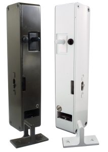

GENERAL INFORMATION
Honeywell Relialign™ RDI Series Residential Door Interlock switches are electromechanical devices designed for use in residential swing door applications, specifically dumbwaiters, lifts for the mobility impaired and swing-door elevators in the USA. In Canada, the RDI is designed for use in residential swing door applications, specifically elevators and dumbwaiters but is not designed for use in lifts for the mobility impaired. The interlock holds the door in place and prevents it from being opened in potentially unsafe conditions (e.g. the elevator/lift car is not present at the door). .
Featuring Honeywell MICRO SWITCH™ switches as an internal solenoid control mechanism, the Relialign™ Series of door interlocks may reduce complexity of the host controller, reduce power consumption, extend solenoid life, and reduce solenoid timeouts. Additional Honeywell MICRO SWITCH™ basic switches are used to indicate door closure and door lock status, providing an extra level of reliability. RDI Series interlocks are configurable and available in left- and right-hand versions, allowing for simplified installation, customization, and retrofitting into current designs.
Honeywell RDI series switches comply with ANSI/ASME A17.1 & A18.1 :2010, (the safety code standards for elevator and escalators), CAN/CSAB44, and UL104 standards. The snap-action cam mechanism reduces adjustment set-up time and the key engagement was designed to minimize maintenance costs due to false alarms. The RDI Series has a robust zinc die cast housing and cover with powder coat finish (white or bronze).

Relialign™ Series residential door interlocks are not a sealed switch. It is not recommended to be used in the areas where liquid or oil may splash.
RISK TO LIFE OR PROPERTY
Never use this product for an application involving serious risk to life or property without ensuring that the system as a whole has been designed to address the risks, and that this product is property rated and installed for the intended use within the overall system.
Failure to comply with these instructions could result in death or serious injury.

MOUNTING
Note mounting dimension drawings for the installation locations. (See Figures 1-2). A separate mounting template provided in the product packaging will guide the installer on how to prepare for the installation of the switch. The switch shall be mounted only in vertical orientation with the conduit opening up. For the switch that use the 6-pin terminals, remove the terminal block assembly inside the housing to reach the mounting holes. Ensure that the terminal block is assembled back onto the housing securely using the screws, once the switch is mounted.
ADJUSTMENT
The mounting template aligns the key to the center of the opening in the interlock housing allowing for door sag over time without any adjustment.
WIRING INSTRUCTIONS
- Remove the cover by unscrewing the cover screw(s).
- CAT5 option only – Plug the mating CAT5 connector into the female receptacle on the RDI interlock.
- Terminal block option – Unscrew the terminal screws. Connect wires per the schematics provided on the inside of the interlock’s cover. Torque all terminal screws with a tightening torque of 0.5 Nm to 0.7 Nm.
- Assemble back the cover. Securely tighten the screw(s). Recommended tightening torque for the cover screw(s) is 1.5 Nm max.
NOTICE FOR EXTERNAL SOLENOID CONTROL OPTION:
The solenoid inside the Relialign RDI Series is rated for continuous duty. However, energy costs can be reduced by ensuring the solenoid is unpowered once the key has entered the locked position. It is recommend that the solenoid controller has a “timing out” feature that automatically cuts power to the solenoid to avoid excessive powered on intervals.
FIGURE 1. RDI LEFT-HAND MOUNTING DIMENSIONS (For reference only) in

RELIALIGN™ RDI SERIES NOMENCLATURE

FIGURE 2. RDI RIGHT-HAND MOUNTING DIMENSIONS (For reference only) in

CLEARANCE BETWEEN HOIST WAY DOORS, LANDING SILLS, AND CAR DOOR
The clearance between the hoistway doors or gates and the hoistway edge of the landing sill shall not exceed 75 mm [3 in]. The distance between the hoistway face of the landing door or gate and the car door or gate shall not exceed 125 mm [5 in]. (See Figure 3).
FIGURE 3. CLEARANCE

FIGURE 4. WIRING SCHEMATIC
RDI PARALLEL CONNECTION, TERMINAL STRIP CONNECTOR

FIGURE 5. WIRING SCHEMATIC
RDI PARALLEL CONNECTION, CAT 5 CONNECTOR

FIGURE 6. WIRING SCHEMATIC
RDI SERIES CONNECTION, TERMINAL STRIP CONNECTOR

FIGURE 7. WIRING SCHEMATIC
RDI SERIES CONNECTION, CAT 5 CONNECTOR

FIGURE 8. CAT 5 CONNECTOR PIN DETAILS

SPECIFICATIONS
Endurance life |
55,000 operations min. |
Operating temperature |
4 °C to 38 °C [40 °F to 100 °F] |
| Storage temperature | -40 °C to 60 °C [-40 °F to 140 °F] |
Standards/approvals |
cULus listed per UL 104 Complies with ANSI/ASME A17.1, A18.1 Complies with CAN/CSA B44 |
| RDI electrical rating | 0.20 A max, 24 Vdc 0.35 A max., 24 Vac, 60 Hz |
WARRANTY/REMEDY
Honeywell warrants goods of its manufacture as being free of defective materials and faulty workmanship. Honeywell’s standard product warranty applies unless agreed to otherwise by Honeywell in writing; please refer to your order acknowledgement or consult your local sales office for specific warranty details. If warranted goods are returned to Honeywell during the period of coverage, Honeywell will repair or replace, at its option, without charge those items it finds defective. The foregoing is buyer’s sole remedy and is in lieu of all other warranties, expressed or implied, including those of merchantability and fitness for a particular purpose. In no event shall Honeywell be liable for consequential, special, or indirect damages.
While we provide application assistance personally, through our literature and the Honeywell web site, it is up to the customer to determine the suitability of the product in the application.
Specifications may change without notice. The information we supply is believed to be accurate andreliable as of this printing. However, we assume no responsibility for its use.
Honeywell serves its customers through a worldwide network of sales offices, representatives and distributors.
For application assistance, current specifications, pricing or name of the nearest Authorized Distributor, contact your local sales office or:
E-mail:
Internet: sensing.honeywell.com
Phone and Fax:
USA/Canada +1-800-537-6945
International +1-815-235-6847
Fax +1-815-235-6545
Sensing and Control
Honeywell
1985 Douglas Drive North
Golden Valley, MN 55422
honeywell.com
50079027-3-EN IL50 GLO Printed in USA
March 2014
Copyright © 2014 Honeywell International Inc. All rights reserved
