Honeywell SLN 700 SmartLine Level Non-Contact Radar Installation Guide


Honeywell SLN 700 SmartLine Level Non-Contact Radar

This document provides descriptions and procedures for the quick installation of Honeywell’s SmartLine Non-Contact Radar Level Transmitters.
The SmartLine Level Non-Contact Radar is available as a family of SLN72x models for liquid and solid applications.
Copyrights, Notices and Trademarks
Copyright 2020 by Honeywell
Revision 1.0, July 2020
Trademarks
SFC, SmartLine, ST 800 and ST 700 are U.S. registered trademarks of Honeywell Inc.
HART® and FOUNDATION™ are trademarks of the FieldComm Group™
Documentation
To access complete documentation, including language variants, scan the QR code below using your smart phone/device or QR code scanner.
Go to the APP store for your free Smartphone QR scanner
Or you can follow the URL to access the online SmartLine HUB page.
The HUB page will contain direct links to open SmartLine product documentation.
https://hwll.co/SmartLineHUB
INTRODUCTION
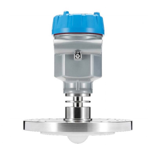
The Smartline SLN700L is available for both liquid and solid non-contact radar level measurement. Each model is available with a range of flange or threaded antenna, lens diameters, process connection, and accessories to suit most applications. Mounting the Transmitter
INSTALLATION
Evaluate the site selected for the SmartLine SLN700 installation with respect to the process system design specifications in table 1. Please note that the display can become unreadable below -20C (-4°F) but it will recover once the temperature increases.
Operating conditions
Table 1: Operating Conditions
| P arameter |
Operative Limits |
T r ansportation and Storage | ||
| ° C | ° F | ° C | ° F | |
| A m b i ent Temperature 1 | -25 to 80 | -13 to 176 | -40 to 80 | -40 to 176 |
| H u m i d ity %RH | 0 to 100 | 0 to 100 | ||
Process Connector
The 80 GHz non-contact radar transmitter has three different series of products and associated process connections.
Table 2: Process Connectors
| S eries | M edium | A pp lications | P r o cess connections |
| 82 Series |
Liquid | Strong corrosive liquid vapors or foam | Flange options |
| 83 Series |
Liquid | Strong corrosive or pressure resistant liquid | Thread options |
| 87 Series |
Solid | Storage vessel/proces s vessel or high dust applications | Flange options |


For list of all options and accessories please refer to the product specifications, which is available, here: https://www.honeywellprocess.com/smartline-level-transmitter.aspx.
MOUNTING THE TRANSMITTER
There should be no obstacles in the area radiated by the transmitted microwave beam from the lower edge of the antenna to the material surface to be measured within the cone angle of the radar beam. These obstacles include ladders, limit switches, heating equipment, supports, etc. When these are unavoidable, the gauge offers background subtraction (“Virtual Echo Learning”) so that obstacles will be ignored during level measurement. In addition, please note that the microwave beam should not intersect with tank fluid in or out flows. In addition, the highest liquid or solid tank level should not encroach into the upper blocking distance of the gauge
(typically a few cm). (see Figure 1), The instrument should be kept at a certain distance from the tank wall and the transmitting antenna should be perpendicular to the measured material surface as much as possible.
The instruments installed in a hazardous classified area shall follow the local national installation regulations.
The reference plane for measurement is the sealing surface of threads or flanges.

- Near (blocking) distance
- Far distance
- Distance at which sensor reads 100% level (or current)
- Distance at which sensor reads 0 % level (or current)
Installation position
The minimum distance between the antenna and tank wall is variable for different antenna. Please refer to Table 3.to calculate the minimum distance for your particular model. In no instance, should the instrument be mounted closer than 200 mm to the tank wall.

- Reference plane
- Center of the vessel or symmetry axis
Table 3: Minimal distance to tank wall
| S L N 700 Model | M in distance to tank wall |
| 83A | 1/5 × Tank Height |
| 82A 82B 83B 83C | 1/10 × Tank Height |
| 82C 82D 83D 83E 87A 87B 87C 87D |
1/20 × Tank Height |
For a conical vessel with a flat tank top, the best installation position of the instrument is the top center of the vessel, which ensures that the bottom of the container is measured.

Nozzle installations
In the case of a tank fluid or solid with good reflection properties (high dielectric constant), the sensor may be mounted on a nozzle. The background subtraction (“virtual echo learning”) feature can further reduce false echoes from nozzle openings.
Table 4 shows detail of the size limitations of the nozzle.

Table 4: Nozzle specification table
| N o zzle Diameter d ( mm ) | M aximum Nozzle Height h ( mm ) | |||
| 83A | 82A 82B
83B 83C |
82C 82D
83D 83E |
87A 87B
87C 87D | |
| 40 | 150 | NA | NA | NA |
| 50 | 150 | 150 | NA | NA |
| 80 | 200 | 200 | 200 | NA |
| 100 | 300 | 300 | 300 | 300 |
| 125 | 400 | 400 | 400 | 400 |
| 150 | 500 | 500 | 500 | 500 |
If there are agitators in the tank, the instrument should be installed as far away from these as possible. Once the installation is completed, the “”virtual echo learning” should be carried out while the agitators are running. This will eliminate the influence of false echo generated by mixing blades. If foam, strong liquid agitation or only a narrow clear volume is available then the customer should consider a guided wave radar sensor such as the Honeywell SLG-700 series.

Conduit Entry Plugs and Adaptors
Procedures
It is the User/Installer’s responsibility to install the transmitters in accordance with national and local code requirements. Conduit entry plugs and adapters shall be suitable for the environment, shall be certified for the hazardous location when required and acceptable to the authority having jurisdiction for the plant.
CONDUIT ENTRY PRECAUTIONARY NOTICE
THE CONDUIT/CABLE GLAND ENTRIES OF THIS PRODUCT ARE SUPPLIED WITH PLASTIC DUST CAPS WHICH ARE NOT TO BE USED IN SERVICE. IT IS THE USER’S RESPONSIBILITY TO REPLACE THE DUST CAPS WITH CABLE GLANDS, ADAPTORS AND/OR BLANKING PLUGS WHICH ARE SUITABLE FOR THE ENVIRONMENT INTO WHICH THIS PRODUCT WILL BE INSTALLED. THIS INCLUDES ENSURING COMPLIANCE WITH HAZARDOUS LOCATION REQUIREMENTS AND REQUIREMENTS OF OTHER GOVERNING AUTHORITIES AS APPLICABLE

Use the following procedures for installation.
Conduit Entry Plugs
| S tep | A ction |
| 1 | Remove the protective plastic cap from the threaded conduit entry. |
| 2 |
To ensure the environmental ingress protection rating on tapered thread (NPT), a non-hardening thread sealant may be used. |
| 3 |
Thread the appropriate size conduit plug (M20 or ½” NPT) into the conduit entry opening. Do not install conduit entry plugs in conduit entry openings if adapters or reducers will be used. |
| 4 |
Tighten adapters according to the following torque: Torque: 32 Nm or 24 lb-ft |
Note: Plugs do not come installed in the housings. All housings come with temporary plastic dust protectors (red or blue) installed and are not certified for use in any installation.
WIRING
Wiring must comply with local codes, regulations and ordinances. Grounding may be required to meet various approval body certification, for example CE conformity. Refer to the SmartLine Level Non-Contact Radar User’s Manual, Document #34-SL-25-13.
HART / 4-20mA Operating Ranges
The Power supply and the output current signal are carried by the same two-core cable. The allowed supply voltage range is 12V to 30Vdepending on loop resistance. There must always be between 12V and 30V on the transmitter terminals, regardless of loop current. A safety barrier (refer to Table 5 for detailed specification) should be placed between the power supply and instrument for the intrinsically safe version.
The grounding mode of current output can be adopted for the standard instrument, while the floating current output should be adopted for the intrinsically safe instrument. Normally, the grounding terminals can be connected to the grounding point of tank or an available nearby ground in case of plastic tank.
Maximum Loop Resistance (Ω)

Table 5: Maximum Loop Resistance (Ω)
| S u pp ly Voltage (VDC) | M ax. Loop Resistance ( Ω ) |
| 12 | 0 |
| 17.5 | 250 |
| 23 | 500 |
| 30 | 818 |
A regular two conductor cable can be used as the power supply cable, and the outside diameter of the cable should be (5-9) mm to ensure the sealing of cable entry. The two ends of the shielded cable should be grounded only where allowed by the installation location. In hazardous locations, only one end of the cable can be shielded, typically on the non-hazardous side.
Remove the display to access the wiring connections

Note: For intrinsically safe installations, shield is normally terminated at one end only
Hazardous Locations & Intrinsic Safety
See manual for Special Conditions of safe use
Table 6: Hazardous Location Ratings
| A GENCY | T YP E OF PROTECTION |
| IECEx TUR 20.0056X | Intrinsically Safe: Ex ia IIC T6…T2 Ga Ex ia IIIC T85˚C…T300˚C Da |
| ATEX TÜV 20 ATEX 8576 X |
Intrinsically Safe: II 1 G Ex ia IIC T6…T2 Ga II 1 D Ex ia IIIC T85˚C…T300˚C Da |
Table 7: Intrinsic Safety Entity Parameters
| I n t r insic Safety Entity Parameter | 4-20mA
T erminal 1 & 2 |
RS
485
T erminal 1 & 2 |
RS
485
T erminal 4 & 5 |
| Ui | 30.6V | 26.4V | 6.5V |
| Ii | 131mA | 166mA | 68mA |
| Pi | 1.0W | 1.1W | 111mW |
| Ci | 0 | 0 | 102μF |
| Li | 102μH | 0 | 0 |
Table 8: Process Temperature Vs Temperature Class
| T
r
ansmitter Ambient
temperature ( ℃ ) |
P
r
o
cess Temperature at the
antenna ( ℃ ) |
T emperature Class of entire equipment |
| -40 to +50 | -40 to +50 | T6/85C |
| -40 to +60 | -40 to +95 | T5/100C |
| -40 to +70 | -40 to +130 | T4/135C |
| -40 to +195 | T3/200C | |
| -40 to +200 | T2/300C |
EU Declaration of Conformity
Hereby, Honeywell International Inc. declares that the SLN700 Radar Level Transmitters are in compliance with the directives listed below.
The full text of the EU declaration of conformity is available at the following internet
address:
https://www.honeywellprocess.com/library/support/Public/Documents/50164363.pdf
The SLN700 transmitters comply with the following directives
| D I R E C T I V E | DESC R I P T I ON |
| 2014/53/EU | Radio Equipment Directive |
| 2014/34/EU | ATEX Directive |
| 2011/65/EU & 2015/863 |
Restriction of Hazardous Substances Directive |
EMC Conformity
The SLN700 transmitters comply with the following EMC standards
| STANDARD | DESCRIPTION |
|
EN 301 489-1 V2.2.0 |
ElectroMagnetic Compatibility (EMC) standard for radio equipment and services; Part 1: Common technical requirements |
| EN 301 489-3 V2.1.1 | ElectroMagnetic Compatibility (EMC) standard for radio equipment and services; Part 3: Specific conditions for Short-Range Devices (SRD) operating on frequencies between 9 kHz and 246 GHz |
| EN 302 729 V2.1.1 | Short Range Devices (SRD); Level Probing Radar (LPR) equipment operating in the frequency ranges 6 GHz to 8,5 GHz, 24,05 GHz to 26,5 GHz, 57 GHz to 64 GHz, 75 GHz to 85 GHz |
| EN 302 372 V2.1.1 | Short Range Devices (SRD); Tank Level Probing Radar (TLPR) equipment operating in the frequency ranges 4,5 GHz to 7 GHz, 8,5 GHz to 10,6 GHz, 24,05 GHz to 27 GHz, 57 GHz to 64 GHz, 75 GHz to 85 GHz |
| EN 62311:2008 | Assessment of electronic and electrical equipment related to human exposure restrictions for electromagnetic fields (0 Hz – 300 GHz) |
| T a b l e 9 : Display Men u Tree Basic Settings, Display and Diagnostics | ||||||
| L evel 1 / Menu no | L evel 2 / Menu no. | L evel 3 | L evel 4 | L evel 5 | ||
|
1.Basic Settings |
1.1 Medium |
Liquid |
Rapid Material Change | Y N | ||
| First Echo | Normal Small Big Bigger Biggest | |||||
| Surface Wave | Y N | |||||
| Low DK | Y N | |||||
|
Solid |
Rapid Material Change | Y N | ||||
| First Echo | Normal Small Big Bigger Biggest | |||||
| Large Angle of Repose | Y N | |||||
| Strong Dust | Y N | |||||
| Low DK | Y N | |||||
| 1.2 Unit of measurement | m / ft / inch /cm / mm |
|||||
| 1.3 Near blanking | ||||||
| 1.4 Range | ||||||
| 1.5 Minimum Adjustment | ||||||
| 1.6 Maximum Adjustment | ||||||
| 1.7 Current Output | 4-20mA / 20-4mA |
|||||
| 1.8 Sensor Tag | ||||||
| L evel 1 / Menu no | L evel 2 / Menu no. | L evel 3 | L evel 4 | L evel 5 |
|
2. Display |
2.1 Display Value | Distance / Height / Percent | ||
| 2.2 Language |
Chinese / English | |||
|
3. D iagnostics |
3.1 Choose Curve | Eff Curve / Echo Curve / False Echo / Log curve | ||
| 3.2 Start Simulation | Current/Distance | |||
| 3.3 Sensor Status | T/ DB/Volt/Service Time | |||
| 3.4 Measure status | Max Volt / Min Volt / Min Volt Time |
|||
| 3.5 Peak Values | Max Distance / Min Distance | |||
| 3.6 Calibration Date |
Sales and Service
For application assistance, current specifications, pricing, or name of the nearest Authorized Distributor, contact one of the offices below.
ASIA PACIFIC (TAC)
Australia Honeywell Limited, Phone: +(61) 7-3846 1255, FAX: +(61) 7-3840 6481 Toll Free 1300-36-39-36, Toll Free Fax: 1300-36-04-70
China – PRC – Shanghai, Honeywell China Inc. Phone: (86-21) 5257-4568,
Fax: (86-21) 6237-2826
Singapore, Honeywell Pte Ltd. Phone: +(65) 6580 3278. Fax: +(65) 6445-3033 South Korea, Honeywell Korea Co Ltd. Phone:+(822)799 6114. Fax:+(822) 792 9015
EMEA, Phone: + 80012026455 or +44 (0)1202645583. FAX: +44 (0) 1344 655554 Email: (Sales)
or (TAC)
AMERICAS, Honeywell Process Solutions,
Phone: (TAC) 1-800-423-9883 or 215/641-3610. (Sales) 1-800-343-0228.
Email: (Sales)
or (TAC)
For more information
To learn more about SmartLine Transmitters, visit www.honeywellprocess.com Or contact your Honeywell Account Manager
Process Solutions
Honeywell
1250 W Sam Houston Pkwy S
Houston, TX 77042
Honeywell Control Systems Ltd
Honeywell House, Skimped Hill Lane
Bracknell, England, RG12 1EB
Shanghai City Centre, 100 Jungi Road
Shanghai, China 20061
www.honeywellprocess.com
34-SL 25-14, Rev.2
November 2020
2020 Honeywell International Inc.