Honeywell 366 Series 1103700 Torque Watch Gauge Instruction Manual
Honeywell 366 Series 1103700 Torque Watch Gauge Instruction Manual
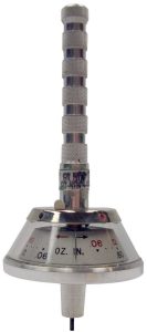

The Series 366 Torque Watch® Gauges are small lightweight instruments designed for measurement of very low values of static torque typically encountered in miniature rotating mechanical systems.
The Series 366 Torque Watches utilize a calibrated helical spring, shaft, and pointer assembly mounted in jeweled bearings to minimize friction.
The 366 series covers a wide range of small torque values. See Table 1 for range, and accuracy.
Torque Range & Accuracy
Torque Range & Accuracy* | ||
| Model | Torque Range | Accuracy |
366-0 |
0.06 – 0.6 oz. in. | ± 5% |
| 366-1 | 0.03 – 0.3 oz. in. | ± 5% |
366-2 |
0.01 – 0.10 oz. in. | ± 10% |
| 366-3 | 0.003 – 0.03 oz. in. | ± 10% |
366-OM |
6 – 42 gm cm | ± 5% |
| 366-1M | 3 – 21 gm cm | ± 5% |
366-2M |
1 – 7.5 gm cm | ± 10% |
| 366-3M | 0.2 – 2.0 gm cm | ± 10% |
366-OSI |
0.4 – 4.0 N-M | ± 5% |
| 366-1SI | 0.2 – 2.0 N-M | ± 5% |
366-2SI |
0.7 – 0.7 N-M | ± 10% |
| 366-3SI | 0.02 – 0.2 N-M | ± 10% |
*Accuracy % Full Scale Value Table 1.
The Series 366 Torque Watch is bidirectional, permitting clockwise or counterclockwise operation over the entire torque range. An internal rotation stop prevents damage from over-torque up to 3 times normal range.
A square drive shaft protrudes from the bottom of the unit to permit coupling to a test piece through one of three miniature adapter chucks furnished with the Series 366 Torque Watch. The adaptor chucks can accommodate shaft diameters from 0.010 to 0.218 in. (0.25 to 5.54 mm).
Chuck Preparation
Determine the shaft diameter of the test piece and select appropriate chuck.
Refer to Table 2 below:
Shaft Diameter | ||
| Chuck | Minimum | Maximum |
| 366-A | .010″ (.25 mm) | .030″ (.76 mm) |
366-B |
.300″ (.76 mm) | .094″ (2.39 mm) |
| 366-C | .094″ (2.39 mm) | .218″ (5.54 mm) |
Using appropriate size drill, preferably mounted in a small lathe, drill out the end of the chuck nearest the set screw to a depth of 0.187 in. (4.75 mm).
Note: Make certain the set screw is removed or backed out of the chuck before drilling the hole.
It is advisable to have a slight chamfer at the edge of the drilled hole to permit easy insertion of the test piece shaft into the chuck.
Operation
- Place the chuck on the shaft of the test piece. Tighten the set screw with hex wrench provided.
- Switch the toggle on the Torque Watch to red (clockwise) or black (counterclockwise) to set direction of rotation.
- To minimize test piece shaft friction caused by radial loads, mount or hold the test piece so its shaft is vertical.
- Insert, but do not “bottom”, the Torque Watch drive shaft in mating plate on chuck and turn the knurled shaft on the Torque Watch. When shaft of test piece moves, read torque value on the Torque Watch scale. See Figure 1.
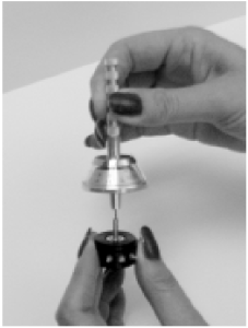
Figure 1.

Notes
- When possible, operate the 366 in a vertical position, shaft down, to minimize errors caused by bearing friction.
- Do not bottom the Torque Watch drive shaft into the chuck. Permit the shaft to “float” in the chuck to avoid loading the bearings.
- Do not lubricate the Torque Watch jewel bearings.
- Additional chuck adapters are available from the factory.
UNITS CONVERSION
UNITS CONVERSION | |||
| Multiply | By | To Obtain | |
| English To English | Ounce Inches Ounce Inches Pound Inches Pound Feet |
6.25 x 10⁻² 5.21 x 10⁻³ 16 192 |
Pound Inches Pound Feet Ounce Inches Ounce Inches |
| English To Metric | Ounce Inches Pound Inches Ounce Inches Pound Inches |
72 1152 720 11520 |
Gram Centimeters Gram Centimeters Gram Millimeters Gram Millimeters |
| Metric To Metric | Gram Centimeters Gram Millimeters Gram Centimeter Kg Centimeter |
10 0.1 10-3 103 |
Gram Millimeters Gram Centimeters Kg-cm gm-cm |
| Metric To English | Gram Centimeters Gram Centimeters Gram Millimeters Gram Millimeters |
1.389 x 10⁻² 8.681 x 10⁻⁴ 1.389 x 10⁻³ 8.681 x 10⁻⁵ |
Ounce Inches Pound Inches Ounce Inches Pound Inches |
| System International | Ounce Inches Gram Centimeters Newton-Meters Newton-Meters |
7.06 x 10⁻³ 9.81 x 10⁻⁵ 141.6 10197 |
Newton-Meters Newton-Meters Ounce Inches Gram Centimeters |
WARRANTY/REMEDY
Honeywell warrants goods of its manufacture as being free of defective materials and faulty workmanship. Contact your local sales office for warranty information. If warranted goods are returned to Honeywell during the period of coverage, Honeywell will repair or replace without charge those items it finds defective. The foregoing is Buyer’s sole remedy and is in lieu of all other warranties, expressed or implied, including those of merchantability and fitness for a particular purpose.
Specifications may change without notice. The information we supply is believed to be accurate and reliable as of this printing. However, we assume no responsibility for its use.
While we provide application assistance personally, through our literature and the Honeywell web site, it is up to the customer to determine the suitability of the product in the application.
Sensing and Control
Honeywell
100 Discovery Way
Acton, MA 01720 USA
Tel: (877) 384-1300;
Fax: (978) 263-0630
www.honeywell.com/sensing/products/di

