Honeywell 940 Series Torque Watch Gauge Instructions


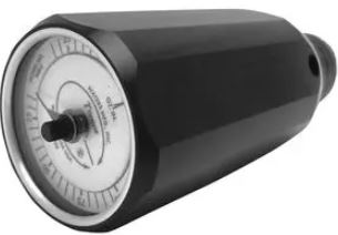
Honeywell 940 Series Torque Watch Gauge

Installation
When making measurements with the Series 940 Torque Watch Gauge, it is important to make certain that the weight of the Torque Watch or the test piece being measured do not effect the measurement. If binding force is applied either to the Torque Watch or test piece, erroneous readings may result. When the test piece being measured is small and unmounted, place the test piece in the Torque Watch chuck, hold the Torque Watch vertically with one hand and turn the test piece with the other hand. See Figure 1.

If the test piece is mounted and has a screwdriver slot, the easiest way to make a measurement is to insert a screwdriver bit in the Torque Watch chuck. The Torque Watch can then be applied to the shaft of the test piece without the application of unwanted force. See Figure 2. Large and unmounted objects can usually be measured by applying the Torque Watch directly to the shaft of the test piece, especially if the object has low friction bearings. In such a case, the weight of the test piece will have a minimal effect on the measurement.

Starting torque is measured by turning the test piece or the Torque Watch until a maximum reading is obtained, after which the reading is typically lower. Removing the chuck and adding
the 3/8″ square socket drive adapter permits the Torque Watch to be used as a torque wrench. When used with the appropriate socket, fasteners, screws and bolts can be tightened accurately to any torque value within the range of the Torque Watch.
The 3/8″ keyed chuck and the 3/8″ square socket drive adapter are both installed by threading onto the shaft (3/8″-24threads). The chuck or the 3/8″ square socket drive adapter are removed from the shaft by rotating the chuck or adapter in a counter-clockwise direction after the shaft has engaged the stop.
When securing the chuck or 3/8″ adapter to the shaft, the tightening torque should be greater than 16 inch pounds but not over 25 inch pounds. This is to prevent loosening when testing torque at 200 oz. in. (On the Model 940-2, for 100 oz. in., torque should be greater than 8 inch pounds but not over 25 inch pounds). Stainless steel pins are employed as stops, permitting overloads of two times the normal range without damage to the Torque Watch.
The bidirectional feature of the 940 Torque Watch permits torque measurements and adjustments to be made in both clockwise and counterclockwise directions. The Series 940 Torque Watch is equipped with a Memory Needle which can save considerable inspecting time on production lines. Because of its inherent accuracy it can also be used in laboratory calibration applications.
The Memory Needle can be defined as a maximum reading pointer or a tolerance indicating pointer, and is used in the following manner:
- As a tolerance indicating pointer: adjust the knurled knob located in the center of the watch crystal, setting the Memory Needle to the desired torque value.
- As a maximum reading pointer: position the Memory Needle below the expected torque range, then measure the torque of the desired test piece as indicated in Figure 1. The final location of the Memory Needle will indicate the highest torque measured.
The Series 940 Torque Watches are provided with two handles which can be inserted into two holes located near the chuck end of the Torque Watch body. The handles increase the operator’s grip radius, enabling the operator to apply full torque with less exertion than if the body alone is gripped. The handles are convenient when several successive measurements are to be taken.
| UNITS CONVERSION | |||
| Multiply | By | To Obtain | |
| English To English |
Ounce Inches Ounce Inches Pound Inches Pound Feet |
6.25 x 10⁻² 5.21 x 10⁻³ 16 192 |
Pound Inches Pound Feet Ounce Inches Ounce Inches |
| English To Metric | Ounce Inches Pound Inches Ounce Inches Pound Inches |
72 1152 720 11520 |
Gram Centimeters Gram Centimeters Gram Millimeters Gram Millimeters |
| Metric To Metric | Gram Centimeters Gram Millimeters Gram Centimeter Kg Centimeter | 10 0.1 10-3 103 |
Gram Millimeters Gram Centimeters Kg-cm gm-cm |
| Metric To English | Gram Centimeters Gram Centimeters Gram Millimeters Gram Millimeters | 1.389 x 10⁻² 8.681 x 10⁻⁴ 1.389 x 10⁻³ 8.681 x 10⁻⁵ |
Ounce Inches Pound Inches Ounce Inches Pound Inches |
| System Internationa l |
Ounce Inches Gram Centimeters Newton-Meters Newton-Meters | 7.06 x 10⁻³ 9.81 x 10⁻⁵ 141.6 10197 |
Newton-Meters Newton-Meters Ounce Inches Gram Centimeters |
WARRANTY/REMEDY
Honeywell warrants goods of its manufacture as being free of defective materials and faulty workmanship. Contact your local sales office for warranty information. If warranted goods are returned to Honeywell during the period of coverage, Honeywell will repair or replace without charge those items it finds defective. The foregoing is Buyer’s sole remedy and is in lieu of all other warranties, expressed or implied, including those of merchantability and fitness for a particular purpose.
Specifications may change without notice. The information we supply is believed to be accurate and reliable as of this printing. However, we assume no responsibility for its use. While we provide application assistance personally, through our literature and the Honeywell web site, it is up to the customer to determine the suitability of the product in the application.
Sensing and Control
Honeywell
100 Discovery Way
Acton, MA 01720 USA
Tel: (877) 384-1300; Fax: (978) 263-0630
www.honeywell.com/sensing/products/di