Bosch 0601083300 Professional Infrared Thermometer GIS 1000 C Instruction Manual
Professional Infrared Thermometer GIS 1000 C


Safety Instructions
All instructions must be read and observed in order for the measuring tool to function safely. The safeguards integrated into the measuring tool may be compromised if the measuring tool is not used in accordance with these instructions.
Never make warning signs on the measuring tool unrecognisable.
SAVE THESE INSTRUCTIONS FOR FUTURE REFERENCE AND INCLUDE THEM WITH THE MEASURING TOOL WHEN TRANSFERRING IT TO A THIRD PARTY.
- Warning! If operating or adjustment devices other than those specified here are used or other procedures are carried out, this can lead to dangerous exposure to radiation.
- The measuring tool is delivered with a laser warning sign (marked in the illustration of the measuring tool on the graphics page).
- If the text of the laser warning label is not in your national language, stick the provided warning label in your national language over it before operating for the first time.
- Do not direct the laser beam at persons or animals and do not stare into the direct or reflected laser beam yourself. You could blind somebody, cause accidents or damage your eyes.
- If laser radiation hits your eye, you must close your eyes and immediately turn your head away from the beam.
- Do not make any modifications to the laser equipment.
- Do not use the laser goggles (accessory) as protective goggles. The laser goggles make the laser beam easier to see; they do not protect you against laser radiation.
- Do not use the laser goggles (accessory) as sunglasses or while driving. The laser goggles do not provide full UV protection and impair your ability to see colours.
- Have the measuring tool serviced only by a qualified specialist using only original replacement parts. This will ensure that the safety of the measuring tool is maintained.
- Do not let children use the laser measuring tool unsupervised.
They could unintentionally blind themselves or other persons. - Do not use the measuring tool in explosive atmospheres which contain flammable liquids, gases or dust. Sparks may be produced inside the measuring tool, which can ignite dust or fumes.
- Do not open the battery. There is a risk of short-circuiting.
- In case of damage and improper use of the battery, vapours may be emitted. The battery can set alight or explode.
Ensure the area is well ventilated and seek medical attention should you experience any adverse effects. The vapours may irritate the respiratory system. - If used incorrectly or if the battery is damaged, flammable liquid may be ejected from the battery. Contact with this liquid should be avoided. If contact accidentally occurs, rinse off with water. If the liquid comes into contact with your eyes, seek additional medical attention. Liquid ejected from the battery may cause irritation or burns.
- The battery can be damaged by pointed objects such as nails or screwdrivers or by force applied externally.
An internal short circuit may occur, causing the battery to burn, smoke, explode or overheat. - When the battery is not in use, keep it away from paper clips, coins, keys, nails, screws or other small metal objects that could make a connection from one terminal to another. A short circuit between the battery terminals may cause burns or a fire.
- Only use the battery with products from the manufacturer.
This is the only way in which you can protect the battery against dangerous overload. - Only charge the batteries using chargers recommended by the manufacturer. A charger that is suitable for one type of battery may pose a fire risk when used with a different battery.
- Protect the battery against heat, e.g. against continuous intense sunlight, fire, dirt, water and moisture. There is a risk of explosion and short-circuiting.
- Remove the rechargeable battery/non-rechargeable batteries from the measuring tool before carrying out work on the measuring tool (e.g. assembly, maintenance, etc.). The battery/batteries should also be removed for transport and storage. There is risk of injury from unintentionally pressing the on/off switch.
- Caution! When using the measuring tool with Bluetooth®, a fault may occur in other devices and systems, aeroplanes and medical devices (e.g. pacemakers, hearing aids). Also, damage to people and animals in the immediate vicinity cannot be completely excluded. Do not use the measuring tool with Bluetooth® in the vicinity of medical devices, petrol stations, chemical plants, areas with a potentially explosive atmosphere and in blasting areas. Do not use the measuring tool with Bluetooth® on aeroplanes.
Avoid using the product near your body for extended periods.
The Bluetooth® word mark and logos are registered trademarks owned by Bluetooth SIG, Inc. and any use of such marks by Robert Bosch Power Tools GmbH is under license. - Protect the measuring tool, particularly the area around the air humidity, ambient temperature and infrared sensor, from moisture, snow, dust and dirt. The reception lens could fog up or become contaminated and distort the measurements. Incorrect settings on the tool and other atmospheric influences may make the measurements inaccurate. Object temperatures could be shown to be hotter or colder than they are, which may present a danger if touched.
- Correct temperature measurements are only possible if the set emissivity and emissivity of the object agree, and the correct reflected temperature is set.
Otherwise, object temperatures could be shown to be hotter or colder than they are, which may present a danger if touched.
Safety Instructions When Using Thermocouples - Thermocouples must not be used in live electrical systems.
This poses a risk to life! - Using a thermocouple means contact with the object measured. Therefore, watch out for potential dangers due to temperature, voltage or a chemical reaction.
Product Description and Specifications
Please observe the illustrations at the beginning of this operating manual.
Intended Use
The measuring tool is intended for contactless measurement of surface temperature, ambient temperature and relative humidity. It calculates the dew point temperature and indicates thermal bridges and mould risk. Mould spores cannot be detected with the measuring tool. However, it can help to detect conditions early on that can encourage mould growth.
The measuring tool may not be used to measure the body temperature of humans or animals or for other medical purposes.
The measuring tool is not suitable for measuring the surface temperature of gases.
Temperature measurement in liquids is only possible using a commercially available thermocouple (connection type K), which can be connected to the measuring tool via the interface (25) intended for this.
Surface temperature can also be measured by touching a surface with a thermocouple.
The light of this measuring tool is intended to illuminate the direct work area of the measuring tool in order to take pictures.
The laser points must not be used as a laser pointer. They are solely for marking out the area being measured.
The measuring tool is suitable for indoor and outdoor use.
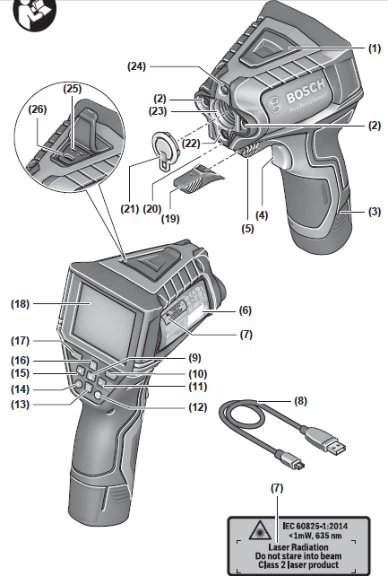
Product Features
The numbering of the product features shown refers to the illustration of the measuring tool on the graphic page.
- Micro USB port flap/thermocouple (type K) connection
- Laser beam outlet aperture
- Battery pack/battery adapter/battery compartment cover release button
- Measure button/on button
- Humidity and ambient temperature sensor
- Serial number
- Laser warning label
- Micro USB cable
- Save/send button (Bluetooth®)
- Right-hand function button
- Right-hand arrow button
- On/off button
- Down arrow button/zoom out
- Light on/off button
- Left-hand arrow button
- Up arrow button/zoom in
- Left-hand function button
- Display
- Protective cap for humidity and ambient temperature sensor
- Carrying strap lug
- Protective cap for infrared reception lens
- Camera
- Infrared beam reception lens
- Light
- Type K connection for thermocouple
- Micro USB port
- Battery adapter covera)
- Battery adapter capa)
- Battery bay
- Batterya)
a) Accessories shown or described are not included with the product as standard. You can find the complete selection of accessories in our accessories range.
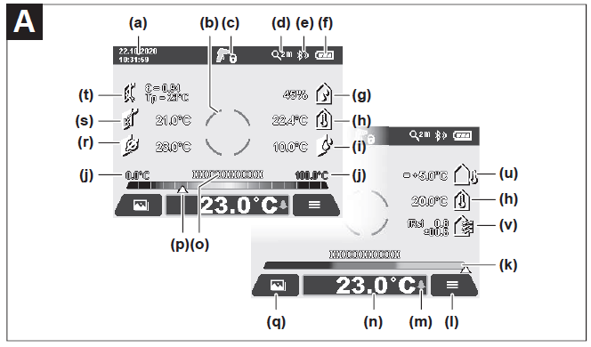
Display elements (see figure A)
(a) Date/time (see “<Time & Date>”, page 27)
(b) Measuring frame (see “Measured area for surface temperature measurements”, page 23)
(c) Status indicator:
Measuring tool is ready to measure; press the measure button (4).
(Continuous) measurement in progress;
lasers are switched on.
Measurement complete, lasers are switched off, measurement results are fixed.
Contact temperature mode, lasers are deactivated, measurement taken only via thermocouple.
(d) Zoom level display (see “Setting the zoom level”, page 24)
(e) Bluetooth® display switched on (see “Data transfer via Bluetooth®”, page 26)
(f) Battery charge indicator
(g) Function indicator/measured value for relative humidity
(h) Function indicator/measured value for ambient temperature
(i) Function indicator/result for dew point temperature
(j) Minimum/maximum measured value for surface temperature during a measurement
(k) Result scale
(l) Menu symbol
(m) Surface temperature alarm display (see “Surface temperature alarm”, page 25)
(n) Measured value
(o) Current mode
(p) Mark for measured value or result (depending on selected mode)
(q) Gallery symbol
(r) Function indicator/measured value for average temperature
(s) Function indicator/measured value for contact temperature
(t) Emissivity/reflected temperature indicator
(u) Set external temperature (thermal bridge mode)
(v) Display of fRsi value with tolerance (thermal bridge mode)
Technical Data


Infra-red thermometer GIS 1000 C
Recommended chargers
A) Plus use-dependent deviation (e.g. reflection, distance, ambient temperature)
B) At an ambient temperature of +20 °C to +23 °C, an emissivity of > 0.999, measuring distance of 0.3 m, aperture of 60 mm
C) At an ambient temperature of +15 °C to +40 °C
D) Values in accordance with the Association of German Engineers’ VDI/VDE 3511 part 4.3 standard (publication date July 2005); applies for 90 % of the measuring signal.
In all areas beyond the values detailed in the technical data, deviations are possible in measurement readings.
E) Refers to infrared measurement, see figure:

F) Only non-conductive deposits occur, whereby occasional temporary conductivity caused by condensation is expected.
G) Depends on battery in use
H) When using Bluetooth® Low Energy devices, it may not be possible to establish a connection depending on the model and operating system.
Bluetooth® devices must support the SPP profile.
The serial number (6) on the type plate is used to clearly identify your measuring tool.
Assembly
Measuring Tool Power Supply
The measuring tool can be operated either with conventional non-rechargeable batteries or with a Bosch lithium-ion battery.
Operation with non-rechargeable batteries (see figure B)
The batteries are inserted into the battery adapter.
- u The battery adapter is intended only for use in designated Bosch measuring tools and must not be used with power tools.
Always replace all the batteries at the same time. Only use batteries from the same manufacturer and which have the same capacity. - Take the batteries out of the measuring tool when you are not using it for a prolonged period of time. The batteries can corrode and self-discharge during prolonged storage in the measuring tool.
Operation with rechargeable battery pack (see figure C) - Use only the chargers listed in the technical data. Only these chargers are matched to the lithium-ion battery of your measuring tool.
Note: The use of batteries unsuitable for your measuring tool can lead to malfunctions or damage to the measuring tool.
Note: The battery is supplied partially charged. To ensure full capacity of the battery, completely charge the battery before the first use.
The lithium-ion battery can be charged at any time without reducing its service life. Interrupting the charging process does not damage the battery.
Operation
Starting Operation
- Protect the measuring tool from moisture and direct sunlight.
- Do not expose the measuring tool to any extreme temperatures or variations in temperature. For example, do not leave it in a car for extended periods of time. In case of large variations in temperature, allow the measuring tool to adjust to the ambient temperature before putting it into operation. The precision of the measuring tool may be compromised if exposed to extreme temperatures or variations in temperature.
- Make sure that the measuring tool is correctly acclimatised.
In case of large variations in temperature, acclimatisation can take up to 60 minutes. This may be the case, for example, if you store the measuring tool in a cool car and then perform a measurement in a warm building. - Avoid hard knocks to the measuring tool or dropping it. After severe external influences and in the event of abnormalities in the functionality, you should have the measuring tool checked by an authorised Bosch aftersales service agent.
Switching on/off
Take the protective cap (21) off the infrared reception lens (23) and the protective cap (19) off the humidity and ambient temperature sensor (5). Make sure that the camera (22), reception lens (23) and sensor (5) are not closed or covered when working, as this will affect the accuracy of the measurements taken.
To switch on the measuring tool, press the on/off button (12) or the measure button (4). A start sequence will appear on the display (18). After the start sequence, the measuring tool will be in the operating mode that was saved the last time the tool was switched off. The lasers are not yet switched on.
Only upon the initial starting operation does the <Tool> menu also appear after the start sequence. In this menu, you can determine the settings of the measuring tool, such as the language of all displays (see “<Tool> submenu”, page 27).
Confirm the selected settings by pressing the right-hand function button (10). You can also change any of the settings later in the <Tool> submenu.
- Never leave the measuring tool unattended when switched on, and ensure the measuring tool is switched off after use. Others may be dazzled by the laser beam.
- Do not direct the laser beam at persons or animals and do not stare into the laser beam yourself (even from a distance).
In the factory setting, the brightness of the display lighting is reduced 30 s after each button press to save energy. Pressing any button will switch the display lighting back to full strength. In the <Light Duration> menu, you can change this lighting time (see “<Light Duration>”, page 27).
To switch off the measuring tool, press the on/off button (12). The measuring tool saves the current operating mode and the settings and then switches off. Put the protective cap (21) back on the reception lens (23) and put the protective cap (19) on the humidity and ambient temperature sensor (5).
Do not switch off the measuring tool by removing the battery pack or battery adapter because this may damage the internal memory in certain cases.
In the main menu, you can set whether and after how long without button press/measurement the measuring tool automatically switches off (see “<Shutdown Time>”, page 27).
The current operating mode and the settings are also saved when the tool switches off automatically.
If the rechargeable battery or the measuring tool are outside the operating temperature specified in the Technical Data, the measuring tool will be switched off automatically after a short warning (see “Errors – causes and corrective measures”, page 28). Allow the measuring tool to reach the correct temperature and then switch it back on.
Measurement preparations
Setting the emissivity for surface temperature measurements To determine the surface temperature, the tool performs a contactless measurement of the natural infrared thermal radiation emitted by the object at which the tool is aimed. To ensure correct measurement, the emissivity setting on the measuring tool must be checked before every measurement and adapted to the measuring object if necessary.
The preset emissivities in the measuring tool are reference values.
You can select one of the preset emissivity levels or enter an exact numerical value. Set the required emissivity via the <Measurement> → <Emissivity value> menu (see “<Main Menu>”, page 27).
- Correct temperature measurements are only possible
if the set emissivity and emissivity of the object
agree, and the correct reflected temperature is set.
Otherwise, object temperatures could be shown to be
hotter or colder than they are, which may present a
danger if touched.
The lower the emissivity, the greater the effect of the reflected
temperature on the measuring result. Always adjust the
reflected temperature when changing the emissivity. Set the
reflected temperature via the
<Measurement> → <Reflected Temp.> menu (see “<Main
Menu>”, page 27).
If there are several objects with a different emissivity being
measured within the measured area identified by the laser,
the temperature measurement can be distorted.
Measured area for surface temperature measurements
The laser points generated by the measuring tool border the
exterior circular measured area. The displayed measured
temperature value shows the average surface temperature
within this area. - Do not direct the laser beam at persons or animals and do not stare into the laser beam yourself (even from a distance).
Increasing the distance between the measuring tool and the object you are measuring will increase the distance between the laser points and consequently the size of the area measured.
If the laser points are difficult to recognise, you can switch on the <Measuring Frame> (b) on the display (see “<Measuring Frame>”, page 27). The measuring frame can be used to indicate the area being measured and helps to improve orientation. The measuring frame may vary from the area being measured depending on the measuring distance.
The area located between the laser points is decisive for the measurement.
Information about the measuring conditions Highly reflective, shiny or transparent surfaces (e.g. highgloss tiles, stainless steel cupboard fronts or saucepans)
may impair the surface temperature reading. If necessary, mask the area to be measured with a dark, matt adhesive tape that conducts heat well. Allow the tape to acclimatise briefly on the surface.
It is not technically possible to perform measurements through transparent materials.
Consequently, the more suitable and stable the measuring conditions are, the more accurate and reliable the results of the measurement will be.
The humidity and ambient temperature sensor (5) can be damaged by chemical contaminants, such as paint or varnish vapours. Infrared temperature measurement is impaired by smoke, vapour or dusty air.
It is therefore important to ventilate the room prior to measuring, especially when the air is contaminated or steamy. For example, do not perform measurements in a bathroom immediately after the shower has been used.
Once ventilated, allow the room to reacclimatise a while until it returns to the usual temperature.
The ambient temperature and relative humidity are measured directly on the measuring tool at the humidity and ambient temperature sensor (5). To achieve meaningful results, do not hold the measuring tool directly over or next to sources of interference such as radiators or open liquids. Do not cover the sensor (5) under any circumstances.
Make sure that a favourable measuring angle is used on reflective surfaces in order to ensure that the thermal radiation reflected by other objects does not distort the result. For example, the reflection of your body heat may interfere with the measurement when measuring head-on from a perpendicular position.
Setting the zoom level
For ongoing measurements and when rendering saved screenshots, the image detail on the display can be shown at 3 different zoom levels: 0.5 m, 2 m and 5 m.
The zoom levels are optimised for the corresponding distance between the measuring tool and the object being measured. At a measuring distance of 2 m, the zoom level “2 m” renders the (typically) best image detail.
The indicator for the current zoom level (d) is shown on the display. To increase the zoom level, press the “Zoom in” (up) arrow button (16); to decrease the zoom level, press the “Zoom out” (down) arrow button (13).
Due to the parallax, the measuring frame (b) only corresponds to the measuring range if the selected zoom level corresponds to the actual measuring distance.
Illuminating the area you are measuring
When measuring in dark areas, you can switch on the light (24) to improve the display of the screen content. This can help you to achieve a better result when saving screenshots.
Press the button (14) to switch the light (24) on or off.
To save energy, the light switches off automatically when the brightness of the display lighting is reduced. You can change how long the display stays lit in the <Light Duration> menu (see “<Light Duration>”, page 27). The light is not automatically switched on when the display lighting is switched back on.
For energy saving reasons, the light is not available when the battery pack’s state of charge is in the critical range.
Measuring functions
Switching Between Individual Modes
Select the required mode with the right (11) or left (15) arrow buttons (the mode is displayed with a short explanation).
To hide the explanation early, press the save button (9). To hide the explanation and immediately start a measurement, press the measure button (4).
Surface temperature mode
Surface temperature mode is used to measure the surface temperature of objects.
In this mode, you can, for example, check radiators or look for overheated machine parts.
You start the measurement by pressing the measure button (4). The measured values shown on the display are continuously being updated. As soon as you let go of the measure button (4), the measurement is interrupted and the lasers are switched off. On the display, the last measurement results are fixed on the (n) indicator. The last measured surface temperature is displayed with the marking (p) on the result scale (k).
Once the difference between the measurements taken is more than 3 °C, the minimum and maximum temperatures measured during the process will appear on the display (j).
This enables you to tell how high the current measured value is in relation to the temperatures already measured.
Thermal bridge mode
The measuring tool can support you in detecting thermal bridges (see “Thermal bridge”, page 28).
Before measurement can be started, the external temperature must first be set. To do so, open the <Main Menu> (see “Navigating in the <Main Menu>”, page 27). Select the <Thermal Bridge> submenu and set the current external temperature. You start the measurement by pressing the measure button (4).
Taking into account the internal ambient temperature and the external temperature, you can determine whether the surface temperature meets the minimum requirements of the heat shield. If the surface temperature falls below the minimum requirements, a structural defect is assumed and a thermal bridge warning given.
Once the measurement has been taken, the surface temperature of the object you last measured is fixed on the display (n), as is the ambient temperature (h). The calculated fRsi value (see “Thermal bridge”, page 28) and its estimated tolerance are shown on the display (v).
The measuring tool displays the interpretation of the values with the marking (p) on the result scale (k):
- Marking (p) in the green range (fRsi value over 0.7, including tolerance): No thermal bridge
- Marking (p) in the yellow range (borderline fRsi value of 0.7): A thermal bridge may be in the measuring range.
- Measurement should be repeated under favourable environmental conditions (e.g. at a lower external temperature).
- Marking (p) in the red range (fRsi value under 0.7, including tolerance): A thermal bridge is probably in the measuring range.
Dew point mode
The measuring tool can support you in detecting places at risk of damage from mould.
The dew point temperature (see “Dew point temperature”, page 29) is calculated from the additionally measured ambient temperature and relative air humidity (see “Relative humidity”, page 29) in this mode. The dew point temperature is compared here with the measured surface temperature and interpreted in terms of the risk of mould formation.
Note that the measuring results always represent only a snapshot based on the current environmental conditions. A forecast for possibly changing environmental conditions cannot be made. If the measurement yields critical results, you should repeat the measurement at different times and under different conditions.
You start the measurement by pressing the measure button (4). The measured values shown on the display are continuously being updated.
Once the measurement has been taken, the surface temperature of the object you last measured is fixed on the display (n), as are the ambient temperature (h) and the relative humidity (g). The calculated dew point temperature is displayed in (i).
The measuring tool automatically helps in the interpretation of the values with the marking (p) on the result scale (k):
- Marking (p) in the green range: There is no risk of mould under the current conditions.
- Marking (p) in the yellow range: The values are borderline; pay attention to the room temperature, thermal bridges and humidity, and repeat the measurement later if necessary.
- Marking (p) in the red range: There is an increased risk of mould because the humidity is too high or the surface temperature is close to the dew point temperature. The respective value flashes in the indicator.
A mould risk warning is given when the surface temperature is 80 % of the dew point temperature.
Note: Mould spores cannot be detected with the measuring tool. It only indicates that mould may form if the conditions remain unchanged.
Contact Temperature Mode
Contact temperature measurement enables the temperature of an object to be measured directly using a commercially available type K shielded thermocouple.
The contact temperature measurement can be a helpful addition to the contactless temperature measurement. Use is particularly recommended in situations in which the infrared measurement has inherent disadvantages, e.g. when measuring temperature in media, liquids, air currents or surfaces with a low emissivity (polished metals).
There are specially optimised sensor geometries for various applications in liquids, in air currents or on surfaces, which allow correct measurement when using a suitable sensor.
Read and observe information from the thermocouple manufacturer if available.
Using a thermocouple principally requires direct contact with the object measured. Pay attention here to potential hazards and the safety instructions.
In this mode, only the temperature of the temperature sensor is measured. Other parameters are excluded here.
Note: Use type K shielded thermocouples only. Measurements
may yield incorrect results if other types of thermocouples
are connected.
Open the flap (1) and connect the thermocouple at the
connection (25).
As soon as a thermocouple is connected, the (n) indicator appears in the display. The measured value of the indicator is continually updated. For the measurement, the measure key (4) must not be pressed in this mode and the lasers are deactivated. To achieve a reliable result, wait for the measured value to stop changing. This can take several minutes depending on the version of thermocouple.
The contact temperature can, however, also be measured in every mode in addition to the surface temperature. Then the measured value is displayed in another place (s). The surface temperature (n) is, however, always used to determine thermal bridges and the risk of mould.
When the thermocouple is removed, the function indicator (s) on the display goes out. Close the flap (1) again after removing the thermocouple
User mode
Surface temperature, ambient temperature and relative humidity are measured in user mode. The dew point temperature and the average temperature (average of the surface temperatures during the measuring period) are calculated from these.
You can hide the following values in the display as required:
Average temperature, relative humidity, ambient temperature and dew point temperature.
To do so, open the <Main Menu> (see “Navigating in the <Main Menu>”, page 27). Select the <User Mode> submenu.
You can switch the indicators for <Average Temp.>, <Humidity>, <Room Temp.> and <Dew Point> on and off here.
For surface temperature measurements, you can choose whether the minimum and maximum values (j) of the result scale (k) are adapted automatically or defined manually. Go to the <User Mode> menu and then the <Scale Range> submenu.
– If you want the values (j) to be determined automatically as in surface temperature mode, select <Auto>. Once the difference between the measurements taken is more than 3 °C, the minimum and maximum temperatures measured during the process will appear on the display (j).
– If you want to define the values manually, select <Preset>. Set the values you require in the <User Mode> menu under <Scale Lower Limit> and <Scale
Upper Limit>. The minimum and maximum values you have set manually will appear on the display (j). This enables screenshots of different measurements to be compared using the marking (p), for example.
Surface temperature alarm
The surface temperature alarm can be used in all modes except contact temperature measurement. You can set a minimum and a maximum temperature If the temperature is below the minimum temperature, the
temperature alarm indicator (m) flashes blue and (if this feature is switched on) a warning signal sounds.
If the temperature is above the maximum temperature, the temperature alarm indicator (m) flashes red and (if this feature is switched on) a warning signal sounds.
To use the surface temperature alarm, open the <Main Menu> (see “Navigating in the <Main Menu>”, page 27).
– Select the <Alarm> submenu.
– Set <Alarm min/max> to <On>.
– Set the minimum temperature under <Alarm min>.
– Set the maximum temperature under <Alarm max>.
The minimum and maximum temperatures will remain saved if you set the alarm to <Off>.
Data transfer
Saving/displaying/sending the results of a measurement After measuring an object, the memory symbol appears on the display to indicate that you can save the results. Press the save/send button (9) to do this.
The results of the measurement are saved as a JPG file (screenshot of the fixed display).

Data Transfer via USB Port
Open the cover on the micro USB port (1). Connect the micro USB port (26) of the measuring tool to your computer via the micro USB cable (8) provided.
Now press the on/off button (12) to switch on the measuring tool.
Open the file browser on your computer and select the GIS 1000 C drive. The saved files can be copied from the internal memory of the measuring tool, moved to your computer or deleted.
As soon as you have finished the required operation, disconnect the drive from the computer following the standard procedure and then use the on/off button (12) to switch the measuring tool off again.
Caution: Always disconnect the drive from your operating system first (eject drive), as failure to do so may damage the internal memory of the measuring tool.
Remove the micro USB cable during the measurement operation and close the cover (1).
Always keep the flap of the USB port closed so that dust and splashes cannot enter the housing.
Note: Use USB to connect the measuring tool to a computer only. The measuring tool may be damaged if connected to other devices.
Data transfer via Bluetooth®
The measuring tool is equipped with a Bluetooth® module which enables the data taken by your measuring tool to be wirelessly transmitted to a mobile device. Special Bosch applications(apps) are available for this use. These can be downloaded from the respective store of the device.

In addition to wireless data transfer, the Bosch applications make it possible for you to use an extended range of functions and facilitate post-editing and forwarding of measured data (e.g. via e-mail). Information about system requirements for a Bluetooth® connection can be found on the Bosch website at www.bosch‑professional.com/thermal.
To switch on the Bluetooth® connection on the measuring tool, open the <Main Menu> (see “Navigating in the <Main Menu>”, page 27) and set up <Bluetooth> <On>. The indicator (e) appears on the display. Ensure that the Bluetooth® interface is activated on your mobile device.
The mobile device and the measuring tool will be paired with each other when the Bosch application is started (providing the Bluetooth® modules are activated). If multiple active measuring tools are found, select the appropriate measuring ool. A connection will be established automatically if only one active measuring tool is found.
Note: When pairing the measuring tool with a mobile device (e.g. smartphone, tablet) for the first time, you may be prompted to enter a PIN code for the measuring tool. If you are, enter “0000”.
When transferring data via Bluetooth®, poor reception conditions can cause time delays between the mobile device and the measuring tool.
<Main Menu>


Measurement Submenu
<Emissivity value> (t)
A selection of saved emissivities is available for some of the most common materials. To make the search easier, the values are combined into groups in the emissivity catalogue.
First select the relevant category and then choose the relevant material in the <Material> menu item. The corresponding emissivity is shown in the line beneath. If you know the exact emissivity of the object being measured, you can also set it as a numerical value in the <Emissivity value> menu item.
If you frequently measure the same materials, you can enter 5 emissivities as favourites and quickly call them up via the bar at the top (numbered from 1 to 5).
<Reflected Temp.> (t)
Setting this parameter can improve the accuracy of the measuring result, especially with low-emissivity (= high-reflection) materials. In some situations (especially in indoor areas), the reflected temperature corresponds to the ambient temperature. If there are objects with greatly deviating temperatures close to highly reflective objects, this value should be adjusted as the measurement may be affected.
<Tool> submenu
Call up the <Main Menu> and select the <Tool> submenu.
This contains the following menu items.
<Language>
In the <Language> menu, you can change the language of all the indicators on the display.
<Time & Date>
To change the time and date shown on the display (a), call up the <Time & Date> submenu. This submenu also allows you to change the time and date format.
To exit the <Time & Date> submenu, press either the left function button (17) to save the settings, or the right function button (10) to discard the changes.
<Unit>
In the <Unit> menu, you can choose whether the temperatures are displayed in <°C> or <°F>.
<Laser>
In the <Laser> menu, you can switch on or off the measuring tool laser. The laser acts as a boundary for the measured area and should, therefore, only be deactivated in exceptional cases.
<Measuring Frame>
In the <Measuring Frame> menu, you can switch the measuring frame (b) on the display on and off.
<Colour Scheme>
In the <Colour Scheme> menu, you can choose the colour of the temperatures and other indicators on the display. The setting will also be applied to saved screenshots.
<Shutdown Time>
In the <Shutdown Time> menu, you can specify after how long the measuring tool will switch off automatically if you do not press any buttons. You can also deactivate automatic switch-off by selecting the <Never> setting. The shorter the automatic switch-off time, the more energy you can save.
<Light Duration>
In the <Light Duration> menu, you can specify after howlong the display lighting will dim if you do not press any buttons on the measuring tool. You can also choose to have the display lit permanently by selecting the <Always> setting.
The shorter the display illumination time, the more energy you can save.
<Audio Signals>
In the <Audio Signals> menu, you can switch the surface temperature alarm sound on and off.
<Delete All Images>
In the <Delete All Images> menu, you can delete all the files in the internal memory at the same time. Press the righthand arrow button (11) for <More> to enter this submenu.
Then press either the right function button (10) to delete all files or the left function button (17) to cancel the process.
<Tool Information>
For information about the measuring tool, call up the <Tool Information> submenu. There you will find the serial number of the measuring tool and the installed software version.
<Factory settings>
Under this menu item, you can reset the measuring tool to factory settings and permanently delete all data. This may take several minutes. Press the right-hand arrow button (11) for <More> to enter this submenu. Then press either the right function button (10) to delete all files or the left function button (17) to cancel the process.
Errors – causes and corrective measures

Glossary of terms
Infrared thermal radiation
Infrared thermal radiation is electromagnetic radiation emitted by every body above 0 Kelvin (−273 °C). The amount of radiation depends on the temperature and the emissivity of the body.
Emissivity
The emissivity of an object depends on the material and the structure of its surface. This specifies how much infrared thermal radiation the object emits compared with an ideal radiant warmer (black body, emissivity ε = 1) and accordingly has a value between 0 and 1.
Reflected Temperature/Reflectivity of an Object
The reflected temperature is the thermal radiation that is not emitted by the object itself. Depending on the structure and material, background radiation is reflected in the object to be measured, therefore distorting the actual temperature result.
Thermal bridge
A thermal bridge is defined as a position on the external wall of a building, where there is a localised increase in heat loss due to a structural defect.
In order to evaluate the thermal bridges, the minimum requirement of a heat shield outlined according to DIN 4108-2 can be used.
According to DIN 4108-2, the minimum requirement of a heat shield is met if the temperature factor fRsi is larger than 0.7.
The temperature factor fRsi is calculated as follows:

The minimum heat shield acts to avoid mould under standard boundary conditions. This avoids buildings being put in danger.
Under standard conditions (external temperature of –5 °C, internal ambient temperature of 20 °C), the surface temperature should not fall under 12.6 °C. This corresponds to an fRsi limit value of 0.7. For as meaningful a result as possible (small uncertainty), the external temperature should be under 10 °C.
Relative humidity
The relative humidity indicates the degree to which the air is saturated with water vapour. The value is indicated as a percentage of the maximum amount of water vapour the air can absorb. The maximum amount of water vapour depends on the temperature: The higher the temperature is, the more water vapour the air can absorb.
If the relative humidity is too high, there is an increased risk of mould. If the relative humidity is too low, it may have a negative impact on your health.
Dew point temperature
The dew point temperature indicates the point at which the water vapour in the air starts to condense. The dew point temperature depends on the relative humidity and the air temperature.
If the temperature of a surface is below the dew point temperature, water will start to condense on this surface.
Condensate on surfaces is one of the main reasons why mould forms.
Maintenance and Service
Maintenance and Cleaning
Keep the measuring tool clean at all times. A dirty infrared reception lens (23) may impair the measuring accuracy.
Wipe off any dirt using a dry, soft cloth. Do not use any detergents or solvents.
When cleaning the measuring tool, ensure that no liquids enter the tool.
Clean the humidity and temperature sensor (5), camera (22), reception lens (23), light (24) and laser outlet aperture (2) particularly carefully. Make sure that there is no lint on the camera, reception lens or laser beam outlet apertures.
Only clean the camera, reception lens and laser beam outlet apertures with cleaning products that are also suitable for camera lenses. Do not attempt to remove dirt from the sensor, camera or reception lens using pointed objects, and do not wipe over the camera and reception lens (risk of scratching).
Do not store the measuring tool for extended periods where the atmospheric humidity is outside the range of 30 % to 50 %. If the measuring tool is stored in conditions that are too damp or too dry, it can result in inaccurate readings.
The air humidity sensor is inherently sensitive to solvents, adhesives and softeners. Being influenced by such substances in the long term can lead to deviations in the measured air humidity.
Do not store the measuring tool in a plastic bag, as the evaporation could damage the humidity and temperature sensor (5). Do not affix any stickers near to the sensor on the measuring tool.
Please contact an authorised Bosch after-sales service centre if you want to have your measuring tool recalibrated.
Only store and transport the measuring tool in the protective bag provided.
If the measuring tool needs to be repaired, send it off in the protective bag.
After-Sales Service and Application Service
Our after-sales service responds to your questions concerning maintenance and repair of your product as well as spare parts. You can find explosion drawings and information on spare parts at: www.bosch-pt.com
The Bosch product use advice team will be happy to help you with any questions about our products and their accessories.
In all correspondence and spare parts orders, please always include the 10‑digit article number given on the nameplate of the product.
Malaysia
Robert Bosch Sdn. Bhd.(220975-V) PT/SMY
No. 8A, Jalan 13/6
46200 Petaling Jaya
Selangor
Tel.: (03) 79663194
Toll-Free: 1800 880188
Fax: (03) 79583838
E-Mail:
www.bosch-pt.com.my
Great Britain
Robert Bosch Ltd. (B.S.C.)
P.O. Box 98
Broadwater Park
North Orbital Road
Denham Uxbridge
UB 9 5HJ
At www.bosch-pt.co.uk you can order spare parts or arrange the collection of a product in need of servicing or repair.