Honeywell TrueZONE HZ221 Zone Panel Professional Installation Guide


Honeywell TrueZONE HZ221 Zone Panel Professional

Need Help?
For assistance with this product please visit http://honeywellhome.com or call Zoning Hotline toll-free at 1-800-828-8367
SPECIFICATIONS AND ACCESSORIES
Input Ratings:
Voltage: 18-30 VAC 50/60 Hz transformer of 40 VA or more.
Current Draw:
Zone Panel: 6.25 VA max.
All VA specifications at 24 VAC.
Wiring:
18–20-gauge solid (not stranded) wire.
Humidity Ratings:
5% to 90% RH non-condensing.
Temperature Ratings:
Shipping: -20° to 150°F (-29° to 66°C)
Operating: -40° to 165°F (-40° to 74°C)
Dimensions:
See below.
Emissions:
Complies with FCC Class B, part 15 requirements.

RECOMMENDED THERMOSTATS, DAMPERS, AND ACCESSORIES
The following are suggested thermostats, dampers, and accessories for use with the TrueZONE panel.
Table 1. Recommended Thermostats.
Compatible thermostats*
TH4210U2002 (Programmable or non-programmable)
TH6210U2001 (Programmable or non-programmable)
TH6220U2000 (Programmable or non-programmable)
TH6320U2008 (Programmable or non-programmable)
TH6220WF2006 (Wi-Fi)
TH6320WF2003 (Wi-Fi)
TH8321WF1001 (Wi-Fi)
THX321WFS2001W (Wi-Fi)
* Note: The HZ221 supports a heat pump with either a heat or cool reversing valve, but the thermostats MUST be configured for a heat pump with cool reversing valve to correctly communicate to the zone panel.
Table 2. Recommended Dampers.
| Type | Damper | Round | Rectangular |
| Zone | Spring-open/ power-closed | ARD | ZD |
| Zone | Power-open/ power-closed | MARD/RRD | |
| Bypass | Static pres- sure regulating damper | CPRD |
Table 3. Maximum Dampers.*
| Ambient Temp. | Maximum Damper VA per Zone |
| 100°F (38°C) | 28.8 |
| 160°F (71°C) | 16.8 |
* Use an SDCR (Slave Damper Control Relay) for additional dampers.
Maximum dampers per panel is limited by transformer size.
Ensure the transformer is large enough to power the panel (6.25 VA) and dampers.
Table 4. Accessories.
| Accessory | Description |
| 40 VA transformer* | AT140A1042* |
| 75 VA transformer | AT175A1008 |
| Discharge Air Temperature Sensor (DATS)* | DATS C7735A1000* |
| SDCR | Slave Damper Control Relay |
* Included in HZ221K kit.
INSTALLATION
- Mount the HZ221 TrueZONE panel near the HVAC equipment; locate it on a wall, stud, roof truss, or cold-air return.
NOTE: The HZ221 TrueZONE panel can be mounted in any orientation; level it for appearance only. - Separate the zone panel cover from the base, and use the base as a template to drill mounting holes. Attach the base to the wall, stud, roof truss, or duct with appropriate screws (not included).
CAUTION: Voltage Hazard.
Can cause electrical shock or equipment damage. Disconnect power before beginning installation. Wire entire panel before applying transformer power. - Install thermostats using instructions provided with thermostats.
Connect thermostat to zone panel. To connect wire to the panel, strip approximately 1/4 in. of insulation and push wire into terminal. To release wire, press the button on top of the terminal. In retrofit applications, trim end of wire if not straight.
If the thermostat has separate E and Aux terminals, install a jumper between the two terminals. - Install dampers using instructions provided with dampers. Connect dampers to zone panel.
NOTE: Multiple dampers can be wired in parallel. - Connect DATS as shown.
- Connect equipment as shown.
- Connect transformer as shown.
The following diagram is an overall view of wiring for a heat pump system as depicted in steps 3–7. Thermostats must be wired/configured for cool changeover “O”, even if equipment uses heat changeover “B.”


OPERATION
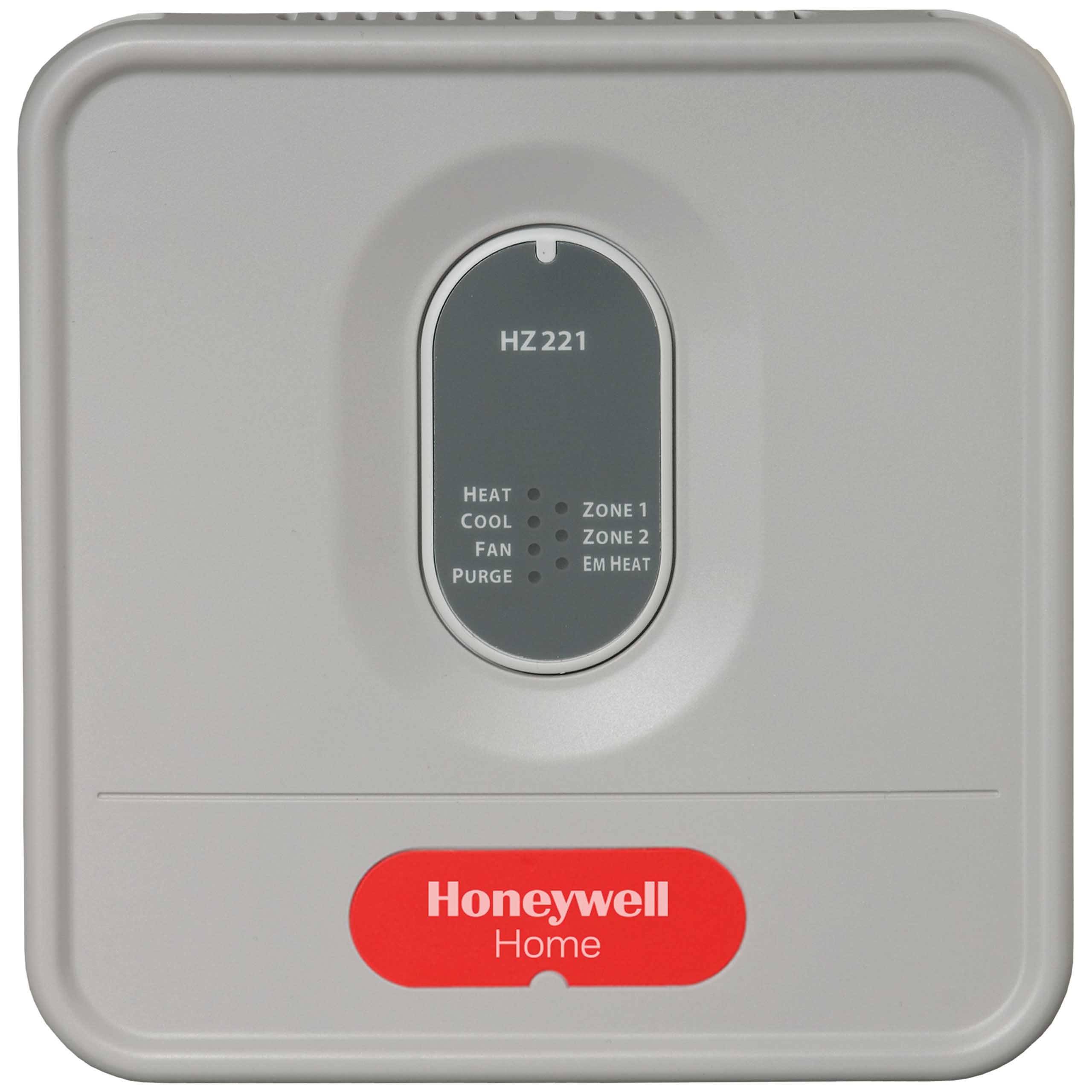
The HZ221 TrueZONE panel contains an LED display that communicates system and zone status. The LEDs indi-cate the following information.
Table 5. LED Operation.
| LED | Description |
| HEAT | Solid when in heat. Blinking when DATS temperature exceeds 120°F (49°C) and calling for heat pump only. Blinking when DATS temperature exceeds 160°F (71°C) and calling for heat pump and auxiliary heat. At 150°F (66°C), auxiliary heat is disabled. |
| COOL | Solid when in cool. Blinking when 45°F (7°C) DATS low limit mode has been reached. |
| FAN | Solid when in operation. |
| PURGE | Solid when in purge (lasts 2 minutes at power-up and after a call for heat or cool). Blinking when the DATS sensor has failed, or the wires are short- ed or open. Will blink for 3 minutes at power-up if DATS is not present. |
| ZONE 1, 2 | Solid green when open or opening. Solid red when closed or closing. Blinking amber when there is a damper or ther- mostat short circuit (circuit breaker trip). |
| EM HEAT | Solid when in Em Heat mode. |


When the zone panel cover is off, the EMERGENCY HEAT/PURGE OVERRIDE but-ton is visible.
When the panel is in Purge (at startup or after a call for heat/cool), pressing this button stops the Purge, which saves time during installation or troubleshooting.
All other times, pressing the button puts the zone panel into Em Heat mode so that all calls for heat are handled by the auxiliary heat.

WARRANTY
Resideo warrants this product, excluding battery, to be free from defects in workmanship or materials, under normal use and service, for a period of five (5) years from the date of first purchase by the original purchaser. If at any time during the warranty period the product is determined to be defective due to workmanship or materials, Resideo shall repair or replace it (at Resideo’s option).
If the product is defective,
- return it, with a bill of sale or other dated proof of purchase, to the place from which you purchased it; or
- call Resideo Customer Care at 1-800-828-8367. Customer Care will make the determination whether the product should be returned to the following address: Resideo Return Goods, 1985 Douglas Dr. N., Golden Valley, MN 55422, or whether a replacement product can be sent to you.
This warranty does not cover removal or reinstallation costs. This warranty shall not apply if it is shown by Resideo that the defect was caused by damage which occurred while the product was in the possession of a consumer.
Resideo’s sole responsibility shall be to repair or replace the product within the terms stated above. RESIDEO SHALL NOT BE LIABLE FOR ANY LOSS OR DAMAGE OF ANY KIND, INCLUDING ANY INCIDENTAL OR CONSEQUENTIAL DAMAGES RESULTING, DIRECTLY OR INDIRECTLY, FROM ANY BREACH OF ANY WARRANTY, EXPRESS OR IMPLIED, OR ANY OTHER FAILURE OF THIS PRODUCT.
Some states do not allow the exclusion or limitation of incidental or consequential damages, so this limitation may not apply to you.
THIS WARRANTY IS THE ONLY EXPRESS WARRANTY RESIDEO MAKES ON THIS PRODUCT. THE DURATION OF ANY IMPLIED WARRANTIES, INCLUDING THE WARRANTIES OF MERCHANTABILITY AND FITNESS FOR A PARTICULAR PURPOSE, IS HEREBY LIMITED TO THE FIVE YEAR DURATION OF THIS WARRANTY. Some states do not allow limitations on how long an implied warranty lasts, so the above limitation may not apply to you.
This warranty gives you specific legal rights, and you may have other rights which vary from state to state. If you have any questions concerning this warranty, please write Resideo Customer Care, 1985 Douglas Dr, Golden Valley, MN 55422 or call 1-800-828-8367.
Resideo Inc., 1985 Douglas Drive North
Golden Valley, MN 55422
69-2200—03 M.S. Rev. 07-19 | Printed in United States
www.resideo.com
This product is manufactured by Resideo Technologies, Inc., Golden Valley, MN, 1-800-828-8367
© 2019 Resideo Technologies, Inc. The Honeywell Home trademark is used under license from Honeywell International Inc.
All rights reserved.