Honeywell Communicating Fan Coil Thermostat Instruction Manual


Honeywell Communicating Fan Coil Thermostat

General
The TF428WNM/U communicating thermostat is designed for 3-speed fan and valve control in fan coil system, including:
- 2-pipe cooling only/heating only/manual changeover
- 4-pipe cooling/heating manual/automatic changeover
- Ventilation mode
- Manual or automatic 3-speed fan control
- Water valve on/off control
The TF428WNM/U is available in Modbus RTU protocol and can be easily integrated into building automation system.
Features
- RS485 interface in Modbus RTU slave mode
- Memorized time off
- Cycle Per Hour (CPH)
- Random startup
- LCD display with simple user interface
- Room temperature or setpoint temperature display selectable
- Manual or automatic fan speed selectable
- Temperature units in either °C or °F
- User setting can be stored when power loss
- Freeze protection function available
- Keypad lock options
Specifications
Physical Layer EIA485
Protocol Modbus RTU
Baud rate 4800/9600(Default)/19200
Parity None
Error checking mechanism CRC
Rated voltage & Frequency 220/230VAC, 50/60Hz
Power consumption <2W
Control PI, On/off output
Accuracy ±1°C at 21°C
Auto cycle times 100,000 times
Manual cycle times 10,000 times
Protection class IP20
Setpoint range 10 ~ 32°C
Display range 0 ~ 37°C
Ambient operating limits 0~ 49°C
Ambient storage limits -30 ~ 60°C
Humidity limits 5~90% RH, non-condensing
Action Type: 1
Pollution Degree 2
Protection against electric shock class Class II
Electronic control software class Class A
Rated impulse voltage: 2500V
Maximum temperature
For relay wiring
Wire sectional area
(Recommendation)
Applied altitude up to 2000m above sea level
Rating capacity
Working current for the whole product : 4(3)A
4A: When the load of the thermostat is resistance
3A: When the load of the thermostat is inductance
For Fan load 3(2)A
3A:when the load is resistance;
2A:When the load is inductance
For Valve load 2(1)A
2A: when the load is resistance;
1A: when the load is inductance
The valve need have overtravel-limit organ to turn off the load.
Model Selection
| Model Number | Backlight | Application | Power Supply | Ventilation Mode | Package |
| TF428WNM/U | White | 2-pipe/4-pipe FCU application | 220/230Vac; 50/60Hz |
Y | Unit Package |
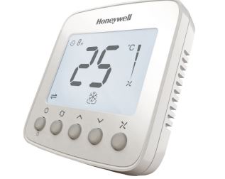
Product Design
Thermostat appearance

LCD display

Dimensions (mm)

Function
Valve Control
Thermostat measures the room temperature via integrated sensor and maintains the setpoint by delivering on/off valve control command output. The fan setting can be selected as manual or automatic 3-speed operation. When in “manual” mode, the fan is switched to the selected speed via control output FH (high), FM (Medium) , FL (Low).
When in “auto“ mode, fan speed depends on the difference between room temperature and setpoint. When room temperature reaches the setpoint, the valve will be closed, and the fan will be closed in the meanwhile.

Memorized Time Off
The time off feature will automatically turn off the thermostat after a selectable amount of time. To change the time setting, press and hold the power button for more than 3 seconds and press “up” and “down” button to change the value when the thermostat is working .
NOTE: The setting range is from 0 to 12 hours. The step is 1 hour and the default value is 0.

Backlight
To turn on the backlight, press any key. The backlight will timeout 8 seconds after the last key is pressed. When in ISU or Installation test mode, the backlight will timeout 60 seconds after the last key is pressed.
Keypad Lockout
Keypad lockout can be set in ISU or over Modbus. The default status is “all keys available”. Keypad lock function can be se-lected as “mode button locked out”, “Fan and mode buttons locked out”, “all buttons (except power button) locked out” and “all buttons locked out”.
Temperature Display
The displayed temperature can be set to room temperature or setpoint. The setting can be changed during ISU (Installation Set Up) process.
Cycle Per Hour (CPH)
CPH function enables the thermostat to open the valve several times per hour as the room temperature approaches to the sepoint.
The value can be changed in the ISU, the default values are 4 for heating and 3 for cooling.
Operating Mode
Comfort Mode
In comfort mode, the setpoint and fan speed can be changed by pressing corresponding buttons. Comfort mode including 2-pipe cooling only/heating only/manual changeover and 4-pipe manual /auto changeover applications.

Ventilation Mode
Press “mode” button to enter “ventilation” mode. In “ventilation” mode, no output for valve while the fan will operate at selected fan speed.
Freeze protection can be selected as disabled or enabled
(default) in the ISU or over Modbus. In freeze protection mode when thermostat is off and the temperature is below 6°C , the thermostat will activate heating mode until the temperature rises to 8°C .


Installation and Wiring
TF428WNM/U can be installed in standard 86 size junction box directly.
The screws must be locked tightly to avoid wire break off from the terminals. The temperature of mounting box and wall should be in the operating temperature range.

Wiring Diagram
2- pipe application
Honeywell VC4013/VN4013/VS4016 Wiring
Honeywell VC6013/VN6013 Wiring


4-pipe application
Note: when in 4-pipe application, the thermostat can not be connected with Honeywell VC6013/VN6013 series motorized valve

Terminal Designations
| Terminal | Description |
| D- | Modbus 485- |
| D+ | Modbus 485+ |
| FL | Low speed fan |
| FM | Medium speed fan |
| FH | High speed fan |
|
V2 |
2-pipe application_VC6013: valve close 4-pipe application_VC4013: cooling valve open |
|
V1 |
2-pipe application_VC4013/VC6013: valve open 4-pipe application_VC4013: heating valve open |
| L | Live wire |
| N | Neutral wire |
ISU (Installation Setup)
Press and hold the “mode” and “up” buttons together for more than 3 seconds to enter or exit ISU. Change the ISU code by pressing the “mode” button and then change the option setting by pressing the “up” and “down” button refer to the following introduction.
| ISU
Code |
Description | Options |
| 0 | Modbus Address | 1~64 1(Default) |
|
1 |
System Type |
0 Heating only |
| 1 Cooling only | ||
| 2 Two pipes heating/cooling manual (Default) | ||
| 4 Fur pipes manual | ||
| 5 Four pipes auto | ||
| 2 |
Temp. Scale |
0 °F |
| 1 °C (Default) | ||
|
3 |
Fan Control Type |
0 Auto only |
| 1 Manual only (3 speed: Low→Med→High→Low) | ||
| 2 Users can choose auto or manual (Default) | ||
|
4 |
Switching Differen- tial for 4 pipe Auto Changeover With Single Setpoint |
1ºC (2ºF) |
| 1.5ºC (3ºF)(Default) | ||
| 2ºC (4ºF) | ||
| 3ºC (5ºF) | ||
| 5 | CPH (Heat) | 1~12 4(Default) |
| 6 | CPH (Cool) | 1~6 3(Default) |
| 7 | Display Temp. Adjustment | -2~2°C, 0.5°C. Default 0°C
(-4~4°F, 1°F. Default 0°F) |
| 8 |
Temp. Display |
0 Room temp. (Default) |
| 1 Setpoint | ||
| 9 | Heating Range Stops | 10~32°C. Default 32°C
(50~90°F. Default 90°F) |
| 10 | Cooling Range stops | 10~32°C Default 10°C
(50~90°F. Default 50°F) |
| ISU
Code |
Description | Options |
|
11 |
Keypad Lockout |
0 All keys are available (Default) |
| 1 Mode button locked out | ||
| 2 Fan and mode buttons locked out | ||
| 3 All buttons locked out ex- cept power button | ||
| 4 All buttons are locked | ||
| 12 |
Freeze Protection |
0 Disabled |
| 1 Enabled (Default) | ||
| 13 |
Power Recovery Status | 0 OFF |
| 1 Previous status (Default) | ||
| 14 |
Modbus Baud Rate |
0 9600( Default) |
| 1 4800 | ||
| 2 19200 |
Modbus Address Table
When the thermostat is integrated into building automation system. Please make configuration refer below list.
| Address Registers | Parameters | Properties and Value | Properties |
| 01 | Power Switch | 0-Off;1-On | R/W |
| 02 | Room Temperature | Room temperature value | R |
| 03 | Temp. Scale | 0-°F;1-°C | R/W |
| 04 | Setpoint | Set temperature value | R/W |
| 05 | Fan Speed | 0-Auto;1-Low speed;2-Med speed;3-High speed | R/W |
| 06 | System Mode | 0-Ventilation;1-Heating;2-Cooling;3-Auto | R/W |
| 07 | V1 Valve Status | 0-Closed;1-Open | R |
| 08 | V2 Valve Status | 0-Closed;1-Open | R |
| 09 | Error Code | 0-None;1-Sensor; 2-EEprom;3-Sensor+ EEprom | R |
| 10 | Fan Status | 0-Off 1-Low 2-Med 3-High | R |
| 11 | Modbus Address | 1~64 1(Default) | R/W |
| 12 | System Type | 0-Heating only;1-Cooling only;2-Two pipes
heating/cooling manual (Default) 4-Four pipes manual;5-Four pipes auto |
R/W |
| 13 | Fan Control Type | 0-Auto;1-Manual;2-Auto+Manual (Default) | R/W |
| 14 | Switching Differential For 4 pipe Auto Changeover With Single Setpoint | 2-1ºC(2ºF); 3-1.5ºC(3ºF); 4-2ºC(4ºF); 5-3ºC(5ºF); | R/W |
| 15 | CPH (Heat) | 1-12 4 (Default) | R/W |
| 16 | CPH (Cool) | 1-6 3 (Default) | R/W |
| 17 | Display Temp. Adjustment | 0~8(-2~2⁰C) step1(0.5⁰C) 4 (Default) 0~8(-4~4⁰F) step1(1⁰F) 4 (Default) | R/W |
| 18 | Temp. Display | 0– Room temp. (Default);1-Setpoint | R/W |
| 19 | Heating Range Stops | 100~320 (10~32⁰C) step5(0.5⁰C) 320 (Default
)
500~900(50~90⁰F) step10(1⁰F) 900 (Default ) |
R/W |
| 20 | Cooling Range Stops | 100~320 (10~32⁰C) step5(0.5⁰C)100 (Default
)
500~900(50~90⁰F) step10(1⁰F) 500 (Default ) |
R/W |
| Address Registers | Parameters | Properties and Value | Properties |
| 21 | Keypad Lockout | 0- All keys are available (Default);1– Mode but- ton locked out;2- Fan and mode buttons locked out;3- All buttons locked out except power but- ton;4- All buttons locked out |
R/W |
| 22 | Freeze Protection | 0- Disabled;1- Enabled (Default) | R/W |
| 23 | Power Recovery Status | 0- OFF;1-Previous Status (Default) | R/W |
| 24 | Modbus Baud Rate | 0-9600 (Default);1-4800;2-19200 | R/W |
| 25 | Time Off Time | 0~12 Step 1 Unit :h | R/W |
| 26 | Remain Time To Turn Off | Remain time to turn off | R |
Note: 1 The parameters are registers,16 bit integer. Modbus Function is 0x01(read),0x06(write sin-gle),0x10(write multiple). 2 Max. 31 devices in one network.
Automation and Control Solutions
Honeywell Environmental and Combustion Controls (Tian Jin) Co., Ltd No. 158, NanHai Road
Tianjin Economic-Technological Development Area
Tianjin, 300457, P.R.C.
Subject to change without notice.