Honeywell VisionPRO Series Programmable Thermostat Installation Guide
Honeywell VisionPRO Series Programmable Thermostat Installation Guide

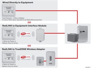
Wired Directly to Equipment

Reference to key features

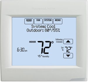
- Current display. Underlined label signifies the current display.
- Mode control buttons. Use to change settings for Fan or System Heat/Cool.
- Menu. Select options to: set schedules, view equipment status, change IAQ settings, access installer options*, etc.
- Current status. Shows system mode (heat/cool), outdoor temperature and humidity (with optional outdoor sensor).
- Current schedule. Shows desired temperature and schedule status.
- Indoor conditions. Shows indoor temperature and humidity.
- Current Time.


Password is the date code.
Getting started
Follow these basic steps to install this thermostat, link it with the wireless accessories, and set installer options
- Installing the thermostat
- Powering optional RedLINK accessories
- Performing initial setup
- Finding your password (Date Code)
- To add or remove RedLINK accessories
- To make changes to Installer Setup
- To perform an Installer Test

Installing the thermostat

- Separate wallplate from thermostat.
If your thermostat has a button along the top of the wallplate, press button on top and pull to remove the wallplate as shown. Updated models do not have this button. On those models pull evenly along the sides and bottom of the thermostat to separate it from the wallplate. - Mount wallplate as shown.
Mount new wallplate using screws and anchors included with the thermostat.
Drill 3/16-in holes for drywall.
Drill 7/32-in holes for plaster. - Connect power.
1.3a Insert supplied AA alkaline batteries for primary or backup power.
1.3b For 24VAC primary power, connect common side of transformer to C terminal. - Wire the thermostat.
Is the thermostat wired directly to the equipment?- If the thermostat is wired directly to the equipment:
- Refer to the table and wiring diagrams on the next page.
- Turn on 24VAC NOW. 24VAC (C wire) is required to connect RedLINK accessories
- If the thermostat is used with an Equipment Interface Module or TrueZONE Wireless Adapter, power the thermostat using Rc and C terminals or with batteries.
- If the thermostat is wired directly to the equipment:
- With thermostat removed from sub-base, insert the coin cell battery.
- Mount thermostat on wallplate.
Updated models do not have hinges. On those models push evenly along the sides and bottom of the thermostat to connect it to the wallplate.


Terminal Designations
| Conventional System | Heat Pump | ||
| Terminal | Description | Terminal | Description |
| C | Common wire from secondary side of cooling transformer (if 2 transformers). | C | Common wire from secondary side of cooling transformer. |
| Rc* | Cooling power. | Rc | Cooling power. |
| R* | Heating power. | R | Heating power. |
| W | Heat Stage 1 | O/B | Changeover valve for heat pumps. |
| W2 | Heat Stage 2 | AUX-E | Backup Heat/Emergency Heat |
| Y | Compressor Stage 1 | Y | Compressor Stage 1 |
| Y2 | Compressor Stage 2 | Y2 | Compressor Stage 2 |
| G | Fan Relay | G | Fan Relay |
| A | Connect to Economizer Module or Lighting Panel (TOD). | L/A | Connect to Compressor Monitor, Zone Panel, Economizer Module or Lighting Panel (TOD). |
| U1 / U1 | Relay for humidification, dehumidification, ventilation, or a stage of heating/cooling. | U1 / U1 | Relay for humidification, dehumidification, ventilation, or a stage of heating/cooling. |
| S1 / S1 | Input for a wired indoor, outdoor or discharge sensor. | S1 / S1 | Input for a wired indoor, outdoor or discharge sensor. |
| K** | Connect to K on C-wire adaptor. | K** | Connect to K on C-wire adaptor. |
* Remove factory installed jumper for two transformer systems.
** The THP9045A1098 C-wire adaptor is used on heat/cool systems when you only have four wires at the thermostat and you would like the thermostat to be powered with a common wire. Use the K terminal in place of the Y and G terminals on conventional or heat pump systems to provide control of the fan and the compressor through a single wire—the unused wire then becomes your common wire. See THP9045 instructions for more information.
POWERED HUMIDIFIER, DEHUMIDIFIER OR VENTILA- TOR

DEHUMIDIFICATION WITH LOW SPEED FAN

DEHUMIDIFICATION WITH LOW SPEED FAN

Wire the thermostat U1 terminal to the low speed fan for dehumidification control at the equipment as shown. The relay can be set to normally open or normally closed in the installer setup.
CONNECTING A HEAT OR COOL STAGE TO U1


Powering optional RedLINK accessories
- Install batteries in RedLINK accessories.
- Portable Comfort Control
- Wireless Outdoor Sensor*
- Wireless Indoor Sensor*
- Wireless Entry/Exit Remote*
- Wireless Vent and Filter Boost Remote*
* Requires setup. See Installer Setup options in Step 3.4.
- Portable Comfort Control
- Connect gateway to internet and connect to power.
- Connect RedLINK Internet Gateway to router or modem with Ethernet cable (RJ45).
- Connect gateway’s power cord to an electrical outlet that is not controlled by a wall switch.

Performing initial setup
Initial setup options define the type of system you are installing:
- Residential or commercial
- Non-zoned or zoned
- Used with or without an Equipment Interface Module (THM5421)
- Used with or without the TrueZONE Wireless Adapter (THM4000)
- Follow prompts on the screen to select the appropriate options.
- When you see the prompt Connect RedLINK Accessories? Touch No or Yes.
- If you select No, continue to Step 3.4.
- If you select Yes, you will be prompted to Press Connect on New Accessories. Continue to Step 3.3.
- Connect each RedLINK accessory.
- While the Press Connect message is displayed (listening mode), press and quickly release the CONNECT button on each new RedLINK accessory.
Listening mode
- After a short delay (up to 15 seconds), check thermostat to confirm the connection of each RedLINK accessory. Touch
- Touch Done at the thermostat after all new RedLINK accessories are connected.
- While the Press Connect message is displayed (listening mode), press and quickly release the CONNECT button on each new RedLINK accessory.
- Finish the initial setup.
Finish the setup by selecting the desired options. Touch Done after you select the last option you want to change.
The thermostat now displays its Home screen and the thermostat setup is complete.


Finding your password (Date Code)
- To add or remove RedLINK accessories
- To make changes to Installer Setup
- To perform an Installer Test
Finding your password
You can find the date code on the back of the thermostat, or
- Touch Menu
- Select Dealer Information.
- Scroll down to see the Date Code.


Linking RedLINK accessories to the thermostat
- Touch Menu.
- Select Installer Options.
- Enter password (date code) and touch Done.
- Select Wireless Manager.
- Select Add Device. The screen displays “Press Connect on New Accessories.” The thermostat is now in listening mode.
NOTE: Accessories must be at least 2 feet away from the thermostat during the linking process.- Press and quickly release the CONNECT button on each new RedLINK accessory.
- After a short delay (up to 15 seconds), check thermostat to confirm the connection of each RedLINK accessory. Touch s or t to review the list.
- Touch Done at the thermostat after all new RedLINK accessories are connected.
- Press and quickly release the CONNECT button on each new RedLINK accessory.


Making changes to Installer Setup and performing an Installer Test
- Touch Menu.
- Select Installer Options.
- Enter password (date code) and touch Done.
- Select Installer Setup or Installer Test.
- Follow prompts on the screen to select the desired setup options or to perform an equipment test.


Use a microSD (secure digital) card to save setup time by loading Installer Setup settings, Dealer Information, Holiday Schedules, and Custom Reminders to multiple thermostats. For troubleshooting help, you can save the thermostat Data Logs (Alerts
Log and Interaction Log) to a microSD card – then view them on your computer. Also use the microSD card to upgrade the thermostat software.
Loading Dealer Information and New Thermostat Software
- Visit http://thermostatsetup.honeywell.com to enter your dealer information or load new thermostat software.
- Connect a microSD USB Adapter to your computer to download the file(s).
- After the file(s) are downloaded, remove the microSD card from the adapter and insert into thermostat.

To use the microSD card in the thermostat

- Slide card into the bottom of thermostat.
- Select the item to load or save.
- Follow the prompts on the screen.
- To add information from the card to the thermostat, select Load from SD Card.
- To put thermostat information on the card, select Save to SD Card.
4 When you are finished, touch Done, then Home, and remove the microSD card.

To replace a thermostat
When you replace a thermostat, you must reset the RedLINK accessories before connecting them to the new thermostat. Follow the instructions below:

At the Portable Comfort Control:
Press and hold the blank space (or arrow) in the lower right hand corner of the screen until the display changes (hold for about 4 seconds). Press REMOVE, then YES to disconnect from the old thermostats. To reconnect the thermostat, go to Step 3.2.
At the Indoor Sensor, RedLINK Internet Gateway, Entry/Exit Remote, Vent-Filter Boost Remote or TrueSTEAM Wireless Adapter:
Press and hold the CONNECT button on the accessory until the status light glows amber (hold for about 10 seconds). To reconnect the thermostat, go to Step 3.2.
At the Equipment Interface Module (EIM):
Press and hold the CONNECT button on the EIM until
the CONNECTED LED glows amber (hold for about 10
seconds). Follow the prompts on the screen to connect
the new thermostat to the EIM.
Specifications and replacement parts
Operating Ambient Temperature
Thermostat: 32 to 120° F (0 to 48.9° C)
Portable Comfort Control: 32 to 120° F (0 to 48.9° C)
Wireless Outdoor Sensor: -40 to 140° F (-40 to 60° C)
Wireless Indoor Sensor: 0 to 120° F (-17.8 to 48.9° C)
-For Optimal Battery Life: 35 to 114° F (1.7 to 45.6° C)
Equipment Interface Module: -40 to 165° F (-40 to 73.9° C)
Return Air Sensor: 0 to 200° F (-17.8 to 93.3° C)
Discharge Air Sensor: 0 to 200° F (-17.8 to 93.3° C)
RedLINK Internet Gateway: 32 to 120° F (0 to 48.9° C)
Operating Relative Humidity
Thermostat: 5% to 90% (non-condensing)
Portable Comfort Control: 5% to 90% (non-condensing)
Wireless Outdoor Sensor: 0% to 100% (condensing)
Wireless Indoor Sensor: 5% to 90% (non-condensing)
Equipment Interface Module: 5% to 95% (non-condensing)
RedLINK Internet Gateway: 5% to 95% (non-condensing)
Physical Dimensions (height, width, depth)
Thermostat: 4-15/16 x 4-5/8 x 1-1/8 inches (126 mm x 118 mm x 29 mm)
Equipment Interface Module: 9-5/16 x 4-13/16 x 1-19/32 inches (91 x 147 x 42 mm)
Wireless Outdoor Sensor: 5 x 3-1/2 x 1-11/16 inches (127 x 89 x 43 mm)
Wireless Indoor Sensor: 2-7/8 x 1-7/8 x 15/16 inches (74 x 48 x 24 mm)
Portable Comfort Control: 6-1/4 x 3-1/8 x 1-5/8 inches (158 x 80 x 38 mm)
RedLINK Internet Gateway: 3-7/8 x 3-9/16 x 1-1/8 (99 x 91 x 29 mm)
RedLINK Communication
Frequency: 900 Mhz frequency range
Re-Sync Time: RedLINK devices re-establish communication within 6 minutes after AC power resumes.
Electrical ratings
| Terminal | Voltage (50/60 Hz) | Max. Current Rating |
| W – OB | 18 to 30 VAC and 750 mVDC | 1.00A |
| Y (cooling) | 18 to 30 VAC | 1.00A |
| G (fan) | 18 to 30 VAC | 0.50A |
| W2 – Aux (heating) | 18 to 30 VAC | 0.60A |
| Y2 (cooling) | 18 to 30 VAC | 0.60A |
| A-L/A (output) | 18 to 30 VAC | 1.00A |
| U1/U1 | 30 VAC max. | 0.50A |
Accessories and replacement parts
| Accessories / Replacement Parts | Part Number |
| Equipment Interface Module | YTHM5421R1010, THM5421R1021 |
| Wireless Adapter for TrueZone, TrueSteam, or extend wireless range of EIM | THM4000R1000 |
| RedLINK Internet Gateway | THM6000R7001 |
| Wireless Entry/Exit Remote | REM1000R1003 |
| Wireless Vent and Filter Boost Remote | HVC20A1000 |
| Portable Comfort Control | REM5000R1001 |
| Wireless Outdoor Sensor | C7089R1013 |
| Wireless Indoor Sensor | C7189R1004 |
| Wired Outdoor Sensor 10k ohm NTC | C7089U1006 |
| Wired Wall-mount Indoor Sensor 10k ohm NTC | C7189U1005 |
| Wired Flush-mount Indoor Sensor 20k ohm NTC | C7772A1004, C7772A1012 |
| Wired Wall-mount Indoor Sensor 20k ohm NTC | TR21 |
| Wired Wall-mount Indoor Sensor 10k ohm NTC | TR21-A |
| Supply or Return Air Sensor 10k ohm NTC | C7735A1000 |
| Supply or Return Air Sensor 20k ohm NTC | C7041 |
| Supply or Return Air Sensor 20k ohm NTC | C7770A1006 |
| Cover Plate (covers marks left by old thermostats) | THP2400A1019 |
| C-wire adaptor | THP9045A1098 |
| Model Numbering | TH8321 | TH8320 | TH8110 |
| Stages | 3H/2C HP 2H/2C CONV |
3H/2C HP 2H/2C CONV |
1H/1C HP 1H/1C CONV |
| Residential or Commercial | |||
| Dual Powered – C Wire or Battery | |||
| Onboard Humidity Sensor | |||
| Number of IAQ Relays | 1 | 0 | 0 |
| Number of Sensor Inputs | 1 | 1 | 1 |
| Economizer / TOD Output | |||
| Works with Optional Equipment Interface Module* | |||
| Works with Optional TrueZONE Wireless Adapter* |

* The relay outputs and inputs on the thermostat do not function when used with an Equipment Interface Module or the TrueZONE Wireless Adapter.
* If the thermostat has been setup WITHOUT an Equipment Interface Module or the TrueZONE Wireless Adapter and you would like to add one, you must reset the thermostat back to factory defaults. Press MENU
- Installer Options > scroll down to select Reset to Defaults.
Perchlorate Material—special handling may apply. See www.dtsc.ca.gov/hazardouswaste/perchlorate

Must be installed by a trained, experience technician. Read these instructions carefully.
Failure to follow these instructions can damage the product or cause a hazardous
condition.
Need Help?
For assistance please visit
http://customer.resideo.com,
or call toll-free: 1-855-733-5465
Golden Valley, MN 55422

©2019 Resideo Technologies, Inc.
This product is manufactured by Resideo Technologies, Inc., Golden Valley, MN, 1 855-733-5465.
The Honeywell Home trademark is used under license from Honeywell International Inc. All rights reserved.