Honeywell CS/CSP/MCS Series Current Switches Instruction Manual


Failure to follow these instructions will result in death or serious injury.
This product can expose you to chemicals including 1,3 Butadiene, which is known to the State of California to cause cancer and reproductive harm. For more information, go to www.P65Warnings.ca.gov
Hazard of electrical shock, explosion, and arc flash

- Follow ALL requirements in NFPA 70E for safe work practices and for Personal Protective Equipment (USA) and other applicable local codes when installing this product
- Only qualified electrical personnel should install this product
- Read, understand and follow all instructions thoroughly
- Install only on insulated conductors
- Lockout and tag out all power sources prior to installation. Use a properly rated voltage sensing instrument to determine no voltage is present
Automated equipment may start without warning
Equipment monitored/operated by this device may start without warning. Keep clear of apparatus at all times
IMPORTANT
- Only qualified trade installers should install this product
- This product is not intended for life-safety applications
- Do not install in hazardous or classified locations
- The installer is responsible for all applicable codes
- This product must be installed in a suitable electrical enclosure
- Clamp sensor around INSULATED CONDUCTOR ONLY, 600VAC MAX to be monitored.

INSTALLATION
CAUTION
Disconnect, lockout and tag out all power supplies during installation
- Determine the mounting location for the sensor near the conductor to be monitored. The sensor should be located AT LEAST 1/2” from any uninsulated conductor.
For CSP split-core sensors, - Sensor features a flexible iris which allows the sensor to hang on the conductor if local codes permit. A bracket is included for screw mounting or attaching to the DIN rail. For screw mounting, drill two 3/32” pilot holes using the bracket as a template; ensure no drill shavings are present in the enclosure.
- Clamp sensor around INSULATED CONDUCTOR ONLY, 600VAC MAX to be monitored through the iris of the sensor. For CSP-NO-AVFD, monitor on LOAD side of VFD drive.
- Snap the sensor into the mounting bracket.
- Wire the output of the sensor to a control panel digital input loop not to exceed 30VAC/DC. Tighten terminals to 3.5 in-lb.
For CS/MCS solid core sensors,
- Drill a single 3/32” pilot hole for mounting the sensor; ensure no drill shavings are present in the enclosure.
- Insert INSULATED CONDUCTOR ONLY, 600VAC MAX to be monitored through the iris of the sensor.
- Reconnect the conductor and torque appropriately.
- Wire the output of the sensor to a control panel digital input loop not to exceed 30VAC/DC wetting voltage. Tighten terminals to 3.5 in-lb.
- Screw mount the sensor to the enclosure.
- Wire the output of the sensor to a control panel digital input loop not to exceed 30VAC/DC. Tighten terminals to 3.5 in-lb.
PRODUCT APPLICATION LIMITATION:
Honeywell products are not designed for life or safety applications. Honeywell products are not intended for use in critical applications such as nuclear facilities, human implantable devices,s or life support. Honeywell is not liable, in whole or in part, for any claims or damages arising from such uses.
WIRING EXAMPLES

NOTE: An AECM sensor is shown here, but the diagram represents the wiring required for all sensors.
TECH TIPS
On low current loads, wrap sensor multiple times to increase sensitivity

Do not exceed sensor maximum current. The current detected by the sensor will increase 1X with each wrap.
To monitor loads greater than the current sensor maximum rating Use a properly rated 5A CT as shown below

5A CTs can present hazardous voltages. Install CTs in accordance with manufacturers’ instructions. Terminate the CT secondary wiring before energizing the primary conductor.
Table 1. Troubleshooting
| Symptom | Causes | Remedy |
| Sensor output does not change state | Amperage is below sensor minimum threshold | Loop monitored conductor multiple turns through sensor. See Tech Tips |
| Incorrect control wiring | Ensure control loop voltage is present | |
| Testing with ohm meter yields incorrect results | Solid-state output may show approx. 1 ohm or less. | |
| Adjustable CT and AECM: Adjustment incorrect | See Adjustable Conventional Calibration or AECM setup procedure | |
| AVFD: Minimum frequency too low. | Drive must ramp to 40Hz min. for the sensor to alarm. |
RECYCLING
The product should not be thrown away in the regular trash. Instead, it should be recycled according to the local municipality.
CSP-NO-F / CS-NO-F OPERATION

The CSP-NO-F-200A output changes state whenever current above 0.35A is present; THE CS-NO-F-50A output changes state above 0.25A. This provides “go/no” status on loads that are not subject to mechanical failures.
Typical on/off status applications include:
- Lighting circuits
- Heater elements
- Direct drive fans (e.g. exhaust fans)
- Process motors
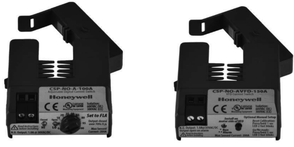
CSP-NO-A / MCS-NO-A UNPOWERED CALIBRATION
Adjust knob on the sensor to motor full load amperage (FLA) as indicated on motor nameplate or overload protection device.

The sensor scale is pre-calibrated for motors operating at a minimum of 75% FLA.
On startup, the sensor output will close when the monitored current exceeds 70% FLA, and open if the current is below 60% FLA to indicate load loss (broken belt, coupling shear, etc.)
For lightly loaded (oversized) motors operating below 75% FLA, the sensor should be set to actual FLA to ensure positive status detection and avoid nuisance alarms.
Smaller (less than 5HP) motors and/or lightly loaded motors may not have sufficient reduction in amperage (below 60% FLA) for the sensor to detect belt loss immediately. The sensor will detect the belt loss when the motor is restarted, as long as the unloaded motor current is below 70% FLA.
For improved performance on small and lightly loaded motors, consider the following options:
1. Use lower current models CSP-NO-A-100A or MCSNO-A-50A for improved calibration resolution.
2. Perform conventional calibration.
CSP-NO-A / MCS-NO-A
CONVENTIONAL CALIBRATION
Follow all safety precautions outlined in this manual. Follow ALL requirements in NFPA 70E for safe work practices and for Personal Protective Equipment (USA) and other applicable local codes when installing this product.
Read all warnings carefully.
1. Adjust knob on the sensor to maximum FLA. (Fully clockwise)
2. With the motor operating normally, adjust the knob SLOWLY counter-clockwise until the “Hi” LED is lit.

Fig. 1. Normal Operation
1. Set knob to motor FLA.

Fig. 2. Small / Lightly Loaded Motor Operation
Set knob proportionally below FLA.
Belt loss will be detected on restart.
Perform Conventional Calibration for best results.
ECM MOTOR APPLICATIONS
ECM stands for Electrically Commutated Motor. These motors are gaining popularity due to their energy savings capability for applications that don’t require the motor to always run at full speed by allowing the end-user to reduce the speed of the motor. It is important to consider the quiescent or standby current draw of an ECM from the onboard electronics. This stand-by current draw typically ranges from 250mA to 500mA and varies by manufacturer. This stand-by current can sometimes be enough to cause
a sensitive current sensor to be in the ON state even when the motor is not actually running giving a false indication. In order to prevent this the current sensors turn-on
current must be higher than the ECM stand-by current.
Honeywell’s Adjustable Turn-On ECM Current Switch allows you to set/adjust your turn-on threshold appropriately for your application. Set the dial so that the turn-on amperage is slightly higher than your ECM standby current. This will typically be around 400mA.

On startup, the sensor output will close when the monitored current exceeds the dial setting, and open if the monitored current is below the dial setting minus the fixed hysteresis value of the current switch.
CSP-NO-AECM SETUP
(RECOMMENDED)
Follow all safety precautions outlined in this manual. Follow all requirements in NFPA 70E for safe work practices and for Personal Protective Equipment (USA) and other applicable local codes when installing this product.
Read all warnings carefully.
- With ECM powered on but not running measure the ECM current draw with a meter capable of measuring current.
- Turn the power off to ECM and set the dial on the current sensor to a value slightly higher than what you measured in step 1. For example, measurement of 500mA from the meter set the dial to about 600mA.
- Power on ECM and verify OPEN LED is on.
- Next, run ECM at minimum speed and verify CLOSED LED is on.
- Stop ECM but leave powered on and verify OPEN LED is on.
- The setup is now complete. You may need to repeat steps 1 through 5 above during the initial setup to get the correct setting. Once adjusted the Honeywell ECM current switch will provide a true status output as shown in the chart above.
CSP-NO-AECM SETUP (ALTERNATE)
Follow all safety precautions outlined in this manual.
Follow all requirements in NFPA 70E for safe work practices and for Personal Protective Equipment (USA) and other applicable local codes when installing this product.
Read all warnings carefully.
- The dial is set from the factory to a value of about 500mA.
- Once installed on the ECM conductor with your motor STOPPED but powered on, verify the OPEN LED is on. If OPEN LED is off adjust the dial clockwise until the OPEN LED is on.
- Turn the dial counterclockwise until the CLOSED LED is on. This is the turn-on amperage or approximate value of your ECM stand-by current.
- Turn the dial clockwise until the CLOSED LED is off and continue clockwise slightly to give a margin of operation between the on and off states. Leave dial at this setting and you’re done with the current sensor setup.
CSP-NO-AVFD CALIBRATION/TRAINING
No calibration is necessary.
The sensor will automatically detect belt loss on motors operated by variable speed drive after 10 seconds of operation above 40Hz. This is because the device leaves the factory in the 40Hz training mode.
OPTIONAL MANUAL SETUP: To reset and restart calibration/training, press/hold the button for 1 second(40Hz mode) or 3 seconds (50Hz mode). LED will make 4 blinks in 5 seconds which indicates the device is in “Training” mode. Operate motor above 40Hz for 10 seconds (40Hz mode) or 50Hz for 10 seconds (50Hz mode), recommend 45Hz and 55Hz respectively.
To activate go/no mode, press/hold the button for 5 seconds. LED will make 3 fast blinks.

CSP-NO-AVFD OPERATION

The CSP-NO-AVFD-150A utilizes a proprietary sensing algorithm to detect belt loss on motors operated by variable frequency drives.
Reliable operation requires variable frequency drive to increase frequency to a minimum of 40Hz when the load is lost.
Typical load status applications include:
- Proof of flow
- Belt-loss detection
- Coupling shear
Table 2. Specification by Product
| Product Number | Trip Point | Core Type | Max Current |
| CS-NO-F-50A | Fixed, 0.25A | SOLID | 50A |
| CSP-N 0 F-200A | Fixed, 0.35A | SPLIT | 200A |
| MCS-NO-A-50A | Adjustable, 0.75-50FLA | SOLID | 50A |
| CS-NO-A-50A | Adjustable, 0.75-50FLA | SOLID | 50A |
| CSP-NO-A-100A | Adjustable, 0.50-100FLA | SPLIT | 100A |
| CSP-NO-A-50A | Adjustable, 0.45-50FLA | SPLIT | 50A |
| CSP-NO-A-150A | Adjustable, 0.50-150FLA | SPLIT | 150A |
| CSP-NO-AECM-200A | Adjustable, 0.25-3A Trip | SPLIT | 200A |
| CSP-NO-AVFD-150A | Automatically detected above 40 Hz | SPLIT | 150A |
SPECIFICATION
Maximum surrounding air ambient, 60 ° C. For use in Pollution Degree 2 environment.
FIXED CURRENT SWITCHES
Output Type
NO, solid-state FET
Output Rating
/DC Max.
Temperature Rating
-15~60 ° C
Insulation Class
600V RMS. For use on insulated conductors only!
Use minimum 75 ° C insulated conductor
Sensor Power
Induced
Frequency Range
50/60Hz
Dimensions (LxWxH)
CSP-NO-F-200A: 2.94” x 2.23” x 0.82”
CSP-NO-F-200A: 1.4” H with optional relay module
CS-NO-F-50A: 2.27” x 1.60” x 1.04”
Sensor Aperture
CSP-NO-F-200A: 0.75”
CS-NO-F-50A: 0.52”
ADJUSTABLE CURRENT SWITCHES
Turn-on Amperage CSP-NO-AVFD-150A
1A(30Hz min), 1.5A(20Hz min), 2.5A(10Hz min)
Output Type
NO, solid-state FET
Temperature Rating
-15~60 ° C
Insulation Class
600V RMS. For use on insulated conductors only! Use minimum 75 ° C insulated conductor
Sensor Power
Induced
Frequency Range
50/60Hz
CSP-NO-AVFD-150A: 10 -120Hz; proof of flow loss alarm at 40Hz+
Dimensions (LxWxH)
MCS-NO-A-50A: 1.78” x 1.32” x 0.66”
CS-NO-A-50A: 2.27” x 1.61” x 0.69”
*CSP-NO-A-xxxA / *CSP-NO-AECM-200A: 2.94” x 2.23” x 0.82”
*CSP-NO-AVFD-150A: 2.51” x 2.23” x 0.82”
*1.4” H with optional relay module
Sensor Aperture
MCS-NO-A-50A: 0.3”
CS-NO-A-50A: 0.5”
CSP-NO-A-xxxA / CSP-NO-AECM-200A / CSP-NO-AVFD150A: 0.75”
* Amperage minimum is frequency-dependent, see TurnOn Amperage
In the U.S.:
Honeywell
715 Peachtree Street NE
Atlanta, GA 30308
customer.honeywell.com
® U.S. Registered Trademark
©2020 Honeywell International Inc.
31-00432M—01 M.S. 10-20
Printed in the United States

