Bosch FR5TPCC Front Radar 5 Truck Plus CAN User Manual


Chassis Systems Control
From
Our Reference
XC-DA/ESR1
Robert Binder
FR5TPCC User Manual for Radio International Type Approval
01-December-2021
Model: FR5TPCC
Product: Front Radar 5 Truck Plus CAN CAN
Description of FR5TPCC parts 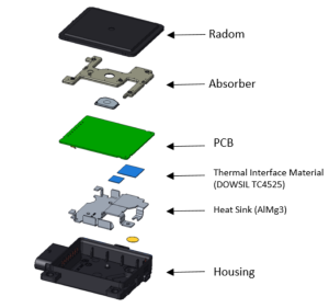

Operation principle of the FR5TPCC
The radar sensor‘s purpose is the detection of objects and measurement of their speed and position relative to the movement of the vehicle in which it is mounted.
FR5TPCC senses targets by emitting much short frequency-modulated waves using the transmit antennas while receiving waves reflected by targets using the receive antennas.
Distance and relative speed are determined by the measurement of the signal’s travel time and Doppler shift. The direction of the target is determined by using the phase difference of the received signal between different Rx antennas.
Using the Bosch chirp sequence radar modulation, the FR5TPCC allows unambiguous determination of relative speed in a single measurement cycle. Therefore, no complex object models are needed for ambiguity resolution.
The values calculated from detected radar reflections are the basis for building a comprehensive model of the sensed environment.
User information
3.1 General description
The FR5TPCC radar sensor and control unit (SCU) contains an FMCW radar transceiver operating in the globally harmonized frequency range of 76.0 – 77.0 GHz. It senses targets by emitting many short frequency-modulated waves using the transmit antennas while receiving waves reflected by targets using the receive antennas. Distance and relative speed are determined via beat frequency (due to traveling time of the waves) and phase differences between ramps (due to change of distance in short time). By using the antenna diagram, the angles of departure and arrival of the radar waves can be determined. Fitted in front of the vehicle, the FR5TPCC monitors continuously vehicle surroundings, supporting driver and vehicle systems with emergency braking, cruise control and distance indicator.
3.2 Areas of application
The FR5TPCC is the base for a range of safety and driver assistance functions. In particular, the
FR5TPCC can be used for the following functions:
3.2.1 Predictive emergency braking system
With the FR5TPCC, vehicle manufacturers can meet the requirements for the automatic emergency braking systems “AEB City” and “AEB Urban” as outlined in the Euro NCAP assessment scheme.
With its predictive emergency braking system, Bosch is helping to prevent rear-end collisions and reduce the severity of accidents. The system becomes active as soon as the vehicle started, and supports the driver at all speeds – both day and night.
If the predictive emergency braking system determines that the distance to the preceding vehicle is becoming critically short, it prepares the braking system for potential emergency braking. If the driver does not react to the hazardous situation, the system warns the driver via an audible and/or visual signal, followed by a short but noticeable brake jerk.
The system then initiates partial braking to reduce the speed and give the driver valuable time to react. As soon as the driver presses the brake pedal, the system provides braking support. To do this, the system continuously calculates the degree of vehicle deceleration required to avoid the collision. If the system detects that the driver has failed to apply sufficient brake force, it increases the braking pressure to the required level so that the driver can attempt to bring the vehicle to a standstill before a collision occurs.
If the driver fails to react to the immediate risk of collision, and the predictive emergency braking system detects that a rear-end collision is unavoidable, it can – working in conjunction with a video camera – automatically initiate full braking. As a result, the vehicle is traveling at significantly reduced speed when the collision occurs, reducing the severity of the crash for the passengers of both vehicles.
If the predictive emergency braking system detects that the distance to a moving or stationary vehicle in front is becoming critically short, it prepares the braking system for a potential emergency braking procedure. If the driver fails to react to the critical situation, the system can automatically initiate full braking in an attempt to prevent the collision. If the rear-end collision is unavoidable, this action can at least minimize the severity of the collision, reducing the risk of injury to the passengers of both vehicles.
3.2.2 Adaptive cruise control (ACC)
The FR5TPCC makes it possible to detect vehicles merging at an early stage – making it the ideal extension of front radar for ACC systems.
The ACC system automatically maintains a set distance from the vehicle ahead by automatically reducing the power to the engine, braking or accelerating. The ACC stop & go variant can also automatically apply the brakes until the vehicle comes to a standstill and will resume automatically when instructed by the driver.
3.2.3 Heading distance indicator
This function measures the distance from the objects around the vehicle and, depending on the speed at which the vehicle is traveling, warns the driver when the safe distance from the vehicle in front is not being maintained. The function does not intervene independently but instead informs the driver of the distance from another vehicle via a visual and/or audible signal.
3.2.4 Sensor data fusion
The FR5TPCC can support sensor data fusion without the need for additional hardware. Sensor data fusion combines the benefits of different sensors and measuring principles in the most effective way possible, providing data that individual sensors working in isolation are unable to generate. The fusion of multiple sensors increases the measurement range, reliability, and accuracy.
Video sensors, such as the multi-purpose camera or the stereo video camera from Bosch, are the ideal supplement to radar technology. Using software algorithms, the fusion of sensor data generates a detailed “image”, which forms the basis for an interpretation of the vehicle`s surroundings.
Sensor fusion enables the implementation of additional assistance and safety functions, such as pedestrian protection (“AEB Pedestrian”). The function for predictive pedestrian protection meets the safety requirements as specified by Euro NCAP. It continually monitors, in combination with a video camera, the area around the vehicle in order to detect impending collisions with pedestrians who are in the path of the vehicle or moving toward it in a way that is likely to present a risk. If the function detects that pedestrians are at risk, it can actively trigger the application of the brakes in order to considerably reduce the risk and the consequences of the collision or to prevent the accident altogether.
Sensor data fusion can also be used to significantly improve the performance of the comfort functions. Thanks to the high degree of lateral measuring accuracy of a video camera, the ACC function is able, for example, to detect vehicles merging at an earlier stage, and therefore respond in a more dynamic manner. The system also ensures that vehicles in front are assigned to the correct lanes, which further enhances ACC functionality, especially when cornering.
3.3 National Statements
3.3.1 European Union
This device should be installed and operated with a minimum distance of 20 cm between the front of the device and the human body.
3.3.2 the United Kingdom
This device should be installed and operated with a minimum distance of 20 cm between the front of the device and the human body.
3.3.3 Canada
This device complies with Industry Canada license-exempt RSS standard(s). Operation is subject to the following two conditions:
(1) this device must not cause interference, and
(2) this device must accept any interference, including interference that may cause undesired operation of the device.
3.3.4 the United States
This device complies with Part 15 of the FCC Rules.
Operation is subject to the following two conditions: this device may not cause harmful interference, and this device must accept any interference received, including interference that may cause undesired operation.
Changes or modifications made to this equipment not expressly approved by Robert Bosch GmbH may void the FCC authorization to operate this equipment.
This equipment has been tested and found to comply with the limits for a Class A digital device, pursuant to Part 15 of the FCC Rules. These limits are designed to provide reasonable protection against harmful interference when the equipment is operated in a commercial environment. This equipment generates, uses, and can radiate radio frequency energy and, if not installed and used in accordance with the instruction manual, may cause harmful interference to radio communications. Operation of this equipment in a residential area is likely to cause harmful interference in which case the user will be required to correct the interference at his own expense.
Radiofrequency radiation exposure Information:
This equipment complies with FCC radiation exposure limits set forth for an uncontrolled environment. This equipment should be installed and operated with a minimum distance of 20 cm between the radiator and your body. This transmitter must not be co-located or operating in conjunction with any other antenna or transmitter.
Vehicle integration
This chapter describes the requirements for all parts mounted in front or around the sensor, like painted bumper, unpainted cover, and emblem/radome, regarding RF integration at 77 GHz with FR5TPCC radar sensors. If these requirements are not met, the sensor performance can be degraded. Values are marked with t.b.c. or t.b.d. showing that they have to be confirmed or defined during the development process.
As product development is an ongoing process, we reserve the right to make amendments in line with technical progress.
The radar sensor performance should be influenced as low as possible by the installation behind a fascia. Therefore the two-way radar loss by the fascia should be as low as possible and the reflection attenuation must fulfill the requirements listed below. Vertical misalignment will cause additional attenuation reducing the maximum range. Horizontal misalignment will cause reduced detection at higher azimuth angles.
Ghost target detection caused by interference signals of multiple reflections at the fascia and metallic parts of the vehicle must be avoided. A simulation can be offered to evaluate the risk and the need of using absorber material to suppress this unwanted signal. Because the threshold of detection is very low, a high attenuation is required. Plastic material can only achieve high enough attenuation if carbon black is added.
4.1 Radar cone
The radar cone describes the zone where the fascia has to be optimized. Any parts of the vehicle inside the radar cone may influence the radar performance. Cables, brackets, bars, etc. should not touch the radar cone. The fascia in this zone may not have bends and edges as well as changes in thickness or material or painting.
Based on the footprint on the top side of the radar PCB, the cone is characterized by a vertical and a horizontal opening angle. The footprint is centered on the sensor housing. A CAD model of the radar cone is available.
The footprint for the radar cone has the following dimensions: (W x H) 55 mm x 55 mm

Figure 2: Footprint of the radar cone. For a better visibility, the footprint is shown on top of the sensor housing.
The horizontal opening angle depends on the angle range that is evaluated by the sensor in azimuth and elevation, whereby the opening angle of the radar cone has to be larger than the angle range that is evaluated. For covered integration, the radar cone is 10° larger than the used angle range that is evaluated by the sensor.
Radar cone:
•±70° (1) (TBC) in the horizontal direction (not including misalignment)
•±20° (TBC) in the vertical direction (not including misalignment)
(1) Valid for an angle measurement range of ±60°
4.2 Fascia design guidelines
Material
Material with a low dielectric constant (r) and low dielectric loss factor tanδ at 77 GHz should be used. Recommended are materials based on polypropylene (PP) and polymethyl methacrylate (PMMA), while materials like polycarbonate (PC) and acrylonitrile butadiene styrene (ABS) are still ok. The material shall be homogenous, compounds including glass fiber, carbon fiber, or metal particles are not recommended.
The fascia shall be designed for radar transparency. The thickness shall be a multiple of the half-wavelength (in the material) to minimize the influence of the fascia. The quality criteria of radar transparency are the reflection coefficient of the radome/fascia. Tolerances of the overall thickness and the dielectric constant of the used material influence the amount of reflection at the radome/fascia. Additional influence occurs due to curvature of the fascia. Therefore the radius has to be as large as possible. With sharp edges, the negative influence will increase significantly. Not allowed are ribs, structures, and steps changing the thickness of the radome/fascia.
Painting
The layer structure of the painting, typically made of three painting layers consisting of primer, base coating, and clear coating, will increase the effective permittivity value εr, eff, and dielectric loss factor tanδ of the painted plate used as fascia.
Fascia Classification (FR5TPCC)
The two-way radar loss caused by fascia should be as low as possible. High losses decrease the sensor performance regarding range and angle estimation. Therefore it is recommended to achieve a two-way radar loss below 3 dB.
4.3 Installation hints
To enable the full performance of the radar sensor, it is recommended to use the following installation hints and guidelines for the RF integration of the sensor.
Maximum angle between radar cone and fascia
The angle α between the radar beam inside the radar cone and the fascia may not be larger than 70° anywhere inside the radar cone

Figure 3: Maximum angle between fascia and radar cone
The minimum distance between sensor and fascia
The minimum distance between the sensor radome and the fascia or any other part of the vehicle may not be smaller than 5 mm.
This is valid for fascia parts fulfilling the following requirements.
Vertical tilt of fascia
The vertical tilt angle between the sensor normal and the surface normal of the fascia shall be in the range according to the following table.


Figure 5: vertical tilt angle of fascia to sensor normal
| Allowed vertical tilt | reflection coefficient | Description | typical application |
| All angles <30° Recommendation: close to 0° <5° >20° and <30° |
<-15 dB <-10 dB |
is achieved when fascia has optimized thickness within a tolerance of ±0.1 mm and permittivity within a tolerance of ±0.02. Dielectric loss factor tanδ shall be <0.01. With such low reflection, a vertical tilt angle close to 0° is recommended. Angles above 30° shall be avoided. This is the case for unpainted or a single e.g. black paint cover. Also, well-designed emblems without air gaps inside may be usable. is achieved when fascia has an optimized thickness within a tolerance of ±0.2 mm and permittivity within a tolerance of ±0.02. Dielectric loss factor tanδ shall be <0.03. With such reflection, a vertical tilt angle of <20° and above 30° must be voided. is achieved when fascia has optimized thickness within a tolerance of ±0.1 mm and permittivity within a tolerance of ±0.2. Dielectric loss factor tanδ shall be <0.03. With such reflection, a vertical tilt angle of <20° and above 30° must be avoided. |
well-optimized unpainted, single painting, emblem painted fascia with single color or unpainted, emblem painted fascia with various colors |
Table: allowed vertical tilt angle of fascia to sensor normal
The examples described in the classification of reflection are derived from the evaluation of flat plates with constant thickness and homogeneous material. Deviations from this situation may cause a change in classification and the vertical tilt angle of the fascia has to be increased.
The curvature of fascia for FR5TPCC
The curvature of the fascia may influence radar performance, especially with low vertical tilt angles. The minimum radius of the curvature shall be according to the following rules:
R > 350 mm, no significant influence expected
R < 350 mm, significant influence possible, has to be evaluated
R < 200 mm, significant influence expected, not recommended
Absorber around the sensor
It is highly recommended to use a cone made of absorber material around the radar cone of the sensor to prevent ghost targets. The design of the absorber cone must fulfill the following design guidelines (reflection from outside the radar cone, multipath reflection).
Reflection from outside the radar cone
Reflections from structures located outside the radar cone have to be avoided.
Furthermore, interference signals picked up by the sensor antennas should be avoided by keeping a minimum distance (d) of 5 mm to 10 mm for parts in front of the sensor. Even with compliance to the radar cone, reflections at parts outside the radar cone may disturb the received signal. Reflections at parts causing an interference signal to the receiving antenna and reflections at parts get to the receiving antenna after a second reflection at the fascia (multipath reflection).
Closed surfaces of brackets and masks made of metal or high reflecting material need a tilt angle being arranged that the reflection is not received by the receiving antennas of the sensor.

Figure 6: Reflection at bracket or mask
For closed surfaces (masks) in azimuth, the angle γ between the mask surface and the normal vector n of the sensor shall be greater than the azimuth opening angle of the keep-out zone. For closed surfaces (masks) in elevation, the angle γ between the mask surface and the normal vector n of the sensor shall be greater than the azimuth opening angle of the keep-out zone.
Multipath reflection
Reflections of incoming signals at bracket or shielding absorber are coming back to the sensor if reflection at the bumper occurs. The figure below shows the situation which should be avoided. The worst-case happens if the combination of the vertical tilt angles of shielding and bumper is γ1 = γ2 / 2 . For a low interference signal the condition shall be: γ1 > γ2 / 2 +10° or γ1 < γ2 / 2 -10°

Figure 7: Requirements for parts outside the radar cone to avoid multipath reflection The same requirements are valid for a horizontal tilt of the fascia.
Calibration
No manual alignment procedure is necessary, as the sensor performs its own internal SW calibration.
References for Chapter 5 & 6 of this document: HW TCD FR5TP (preliminary)
Technical Data
| Product model name: | FR5TPCC |
| Frequency Band: | 76-77 GHz |
| Maximum Transmit Power: Measured mean EIRP | 21.73 dBm |
| Maximum Transmit Power: Measured peak EIRP | 31.00 dBm |