Bosch CR5CBCC Front Radar Sensor User Manual
BOSCH CR5CBCC Front Radar Sensor
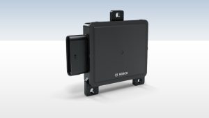

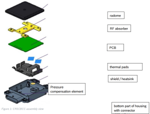
Description of CR5CBCC parts

Explanation of CW Radar function
Continuous-wave radar is a type of radar system where a known stable frequency continuouswave radio energy is transmitted and then received from any reflecting objects. Continuouswave (CW) radar uses Doppler, which renders the radar immune to interference from large stationary objects and slow moving clutter.
Maximum distance in a continuous-wave radar is determined by the overall bandwidth and transmitter power.
This bandwidth is determined by two factors.
- Transmit energy density (watts per Hertz)
- Receiver filter size (bandwidth divided by the total number of filters)
Frequency-modulated continuous-wave radar (FM-CW) – also called continuous-wavefrequency-modulated (CWFM) radar – Pressure compensation element is a short-range measuring radar set capable of determining distance. This increases reliability by providing distance measurement along with speed measurement, which is essential when there is more than one source of reflection arriving at the radar antenna. This kind of radar is often used as “radar altimeter” to measure the exact height during the landing procedure of aircraft. It is also used as early warning radar, wave radar, and proximity sensors. Doppler shift is not always required for detection when FM is used.
In this system the transmitted signal of a known stable frequency continuous wave varies up and down in frequency over a fixed period of time by a modulating signal.
Frequency difference between the receive signal and the transmit signal increases with delay, and hence with distance. This smears out, or blurs, the Doppler signal. Echoes from a target are then mixed with the transmitted signal to produce a beat signal which will give the distance of the target after demodulation.
A variety of modulations is possible, the transmitter frequency can slew up and down as follows:
- Sine wave, like air raid siren
- Sawtooth wave, like the chirp from a bird
- Triangle wave, like police siren in the United States
- Square wave, like police siren in the United Kingdom
Range demodulation is limited to 1/4 wavelength of the transmit modulation. Instrumented range for 100 Hz FM would be 500 km. That limit depends upon the type of modulation and demodulation.
Sawtooth modulation is the most used in FM-CW radars where range is desired for objects that lack rotating parts. Range information is mixed with the Doppler velocity using this technique.
Modulation can be turned off on alternate scans to identify velocity using unmodulated carrier frequency shift. This allows range and velocity to be found with one radar set. Triangle wave modulation can be used to achieve the same goal.
As shown in the figure the received waveform (green) is simply a delayed replica of the transmitted waveform (red). The transmitted frequency is used to down convert the receive signal to baseband, and the amount of frequency shift between the transmit signal and the reflected signal increases with time delay (distance). The time delay is thus a measure of the range; a small frequency spread is produced by nearby reflections, a larger frequency spread corresponds with more time delay and a longer range.

Ranging with an FM-CW radar system: if the error caused by a possible Doppler frequency can be ignored and the transmitter’s power is linearly frequency modulated, then the time delay is proportional to the difference of the transmitted and the received signal at any time
References for chapter 2 of this document:
https://en.wikipedia.org/wiki/Continuous-wave_radar
This work is released under CC-BY-SA: http://creativecommons.org/licenses/by-sa/3.0/
Operation principle of the CR5CBCC
The radar sensor‘s main task is to detect objects and measure their speed and position relative to the movement of the vehicle in which it is mounted.
To do this, the CR5CBCC senses targets by emitting many short frequency modulated waves using the transmit antennas while receiving waves reflected by targets using the receive antennas.
Distance and relative speed are determined via beat frequency (due to travelling time of the waves) and phase differences between ramps (due to change of distance in short time). By using the antenna diagram the angles of departure and arrival of the radar waves can be determined.
Using the Bosch chirp sequence radar modulation, the CR5CBCC allows unambiguous determination of relative speed in a single measurement cycle. Therefore, no complex object models are needed for ambiguity resolution.
The radar reflections (strength, distance and relative speed, angular direction, and derived values) are basis for building a comprehensive model of the sensed environment.
User information
General description
The CR5CBCC radar sensor and control unit (SCU) contains a FMCW radar transceiver operating in the globally harmonized frequency range of 76.0 – 77.0 GHz. It senses targets by emitting many short frequency modulated waves using the transmit antennas while receiving waves reflected by targets using the receive antennas. Distance and relative speed are determined via beat frequency (due to travelling time of the waves) and phase differences between ramps (due to change of distance in short time). By using the antenna diagram, the angles of departure and arrival of the radar waves can be determined.
Using the Bosch chirp sequence radar modulation, the CR5CBCC allows unambiguous determination of relative speed in a single measurement cycle. Therefore, no complex object models are needed for ambiguity resolution. The radar reflections (strength, distance and relative speed, angular direction, and derived values) are basis for building a comprehensive model of the sensed environment.
Fitted in corners of the vehicle, the CR5CBCC monitors continuously vehicle surroundings, supporting driver and vehicle systems at turning or lane change manoeuvers. While fitted in rear of vehicle, at higher speeds, the CR5CBCC operates in long-range mode, monitoring area behind vehicle for small, fast approaching targets (like motorbikes).
Areas of application
The CR5CBCC is the base for range of safety and driver assistance functions. In particular, the CR5CBCC can be used for the following functions:
Blind spot detection
Optical and/or acoustic warning of the driver if a vehicle is detected in the Blind Spot Zone in order to avoid unsafe lane change or turn maneuvers of the driver.
Lane change assist
Optical and/or acoustic warning of the driver if an approaching vehicle is detected in the neighboring lanes in the area behind the Blind Spot Zone in order to avoid unsafe lane change or turn maneuvers of the driver.
Rear Cross Traffic Assist with braking
Optical and/or acoustic warning of the driver on vehicles crossing the estimated path of the ego vehicle in the rear area (e.g. backing out of parking spaces).
Door opening warning
The door opening warning (DOW) feature shall detect target vehicle in the door opening warning zones. DOW feature warns the driver and passengers against collisions that may occur with target vehicle passing the subject vehicle from behind within a specific lateral distance from subject vehicle’s relevant side when subject vehicle is at standstill and the door is to be opened.
It supports the driver and passengers of the subject vehicle when leaving the vehicle.
Rear collision warning
Warning to the target vehicle if it is approaching the subject vehicle from behind and there is a chance of collision.
Front Cross Traffic Assist – Information
Optical visualization of the time based criticality of the approaching vehicle, crossing in front of the vehicle. The front cross traffic assist-Information function is designed to inform the driver at stand-still or during drive-off / acceleration phase at intersection scenarios or while leaving a parking spot.
National statements
Canada
This device complies with Industry Canada license-exempt RSS standard(s). Operation is subject to the following two conditions:
(1) this device must not cause interference, and
(2) this device must accept any interference, including interference that may cause undesired operation of the device.
European Union
This equipment should be installed and operated with minimum distance of 20 cm between the radiator and any person.
United Kingdom
This equipment should be installed and operated with minimum distance of 20 cm between the radiator and any person.
United States
This device complies with Part 15 of the FCC Rules.
Operation is subject to the following two conditions:
(1) this device may not cause harmful interference, and
(2) this device must accept any interference received, including interference that may cause undesired operation.
Changes or modifications made to this equipment not expressly approved by Robert Bosch GmbH may void the FCC authorization to operate this equipment.
This equipment has been tested and found to comply with the limits for a Class A digital device, pursuant to Part 15 of the FCC Rules. These limits are designed to provide reasonable protection against harmful interference when the equipment is operated in a commercial environment. This equipment generates, uses, and can radiate radio frequency energy and, if not installed and used in accordance with the instruction manual, may cause harmful interference to radio communications. Operation of this equipment in a residential area is likely to cause harmful interference in which case the user will be required to correct the interference at his own expense.
Radiofrequency radiation exposure Information:
This equipment complies with FCC radiation exposure limits set forth for an uncontrolled environment. This equipment should be installed and operated with minimum distance of 20 cm between the radiator and your body.
This transmitter must not be co-located or operating in conjunction with any other antenna or transmitter.
Vehicle integration
This chapter describes the requirements for all parts mounted in front or around the sensor, like painted bumper, unpainted cover and emblem/radome, regarding RF integration at 77 GHz with CR5CB radar sensors. If these requirements are not met, the sensor performance can be degraded.
Values are marked with t.b.c. or t.b.d. showing that they have to be confirmed or defined during the development process.
As product development is an on-going process, we reserve the right to make amendments in line with technical progress.
The radar sensor performance should be influenced as low as possible by the installation behind a fascia. Therefore the two-way radar loss by the fascia should be as low as possible and the reflection attenuation must fulfill the requirements listed below.
Vertical misalignment will cause additional attenuation reducing the maximum range.
Horizontal misalignment will cause reduced detection at higher azimuth angles.
Ghost target detection caused by interference signals of multiple reflection at fascia and metallic parts of the vehicle must be avoided. A simulation can be offered to evaluate the risk and the need of using absorber material to suppress this unwanted signal. Because the threshold of detection is very low, a high attenuation is required. Plastic material can only achieve high enough attenuation, if carbon black is added.
Radar cone
The radar cone describes the zone where the fascia has to be optimized. Any parts of the vehicle inside the radar cone may influence the radar performance. Cables, brackets, bars etc.
should not touch the radar cone. The fascia in this zone may not have bends and edges as well as changes in thickness or material or painting.
Based on the footprint on the top side of the radar PCB the cone is characterized by a vertical and a horizontal opening angle. The footprint is centered regarding to the sensor housing. A CAD model of the radar cone is available.
The footprint for radar cone has the following dimensions: (W x H) 55 mm x 55 mm

Radar cone definition for covered installation (CR5CB):
The horizontal opening angle depends on the angle range that is evaluated by the sensor in azimuth and elevation, whereby the opening angle of the radar cone has to be larger than the angle range that is evaluated. For covered integration the radar cone is 10° larger than the used angle range that is evaluated by the sensor.
Radar cone:
- ±80° (1) (tbc) in horizontal direction (not including misalignment)
- ±20° (tbc) in vertical direction (not including misalignment)
(1) Valid for angle measurement range of ±75°
Fascia design guidelines
Material
Material with low dielectric constant (
The fascia shall be designed for radar transparency. The thickness shall be a multiple of the half wavelength (in the material) to minimize the influence of the fascia. The quality criteria of radar transparency is the reflection coefficient of the radome/fascia. Tolerances of the overall thickness and the dielectric constant of the used material influence the amount of reflection at the radome/fascia. Additional influence occurs due to curvature of the fascia. Therefore the radius has to be as large as possible. With sharp edges the negative influence will increase significantly. Not allowed are ribs, structures and steps changing the thickness of the radome/fascia.

Painting
The layer structure of the painting, typically made of three painting layers consisting of primer, base coating and clear coating, will increase the effective permittivity value
Fascia Classification (CR5CB)
The two-way radar loss caused by fascia should be as low as possible. High losses decrease the sensor performance regarding range and angle estimation. Therefore it is recommended to achieve a two-way radar loss below 4 dB in the ranges [-20;+20]° and [+/-60;+/-75]° and 3 dB in
the range [+/-20,+/-60]° t.b.c.. 4 dB attenuation corresponds to a loss of about 20% of sensor range.
Classification of the fascia
| Fascia type | Material characteristic | Reflection and attenuation | ||
| 1. | Unpainted bumper | Optimized thickness within a tolerance ±0.2 mm and permittivity within a tolerance ±0.05. Dielectric loss factor tanδ shall be <0.03. | – Reflection coefficient <-10 dB – 2-way attenuation <4 dB. | |
| 2. | Painted bumper with various colors | Range of the permittivity values between 2.5 and 3.2. | Dielectric loss factor tanδ <0.02 | – Reflection coefficient <-6 dB – 2-way attenuation <4 dB. |
| Dielectric loss factor tanδ >0.02 | – Reflection coefficient >-6 dB – The attenuation may exceed the maximum allowed limit. | |||
The examples described in the classification of the fascia are derived from evaluation of flat plates with constant thickness and homogeneous material. Deviations from this situation may cause a change in classification.
Surface Properties of the fascia
The surfaces of the fascia shall not exceed an average roughness height of 20 µm (corresponding to ISO 1302 class N10; VDI 3400 class 45).
Installation Hints
To enable the full performance of the radar sensor, the following installation hints and guidelines for the RF integration of the sensor must be used.
Maximum angle between radar cone and fascia
The angle α between the radar beam inside the radar cone and the fascia may not be larger than 80° anywhere inside the radar cone

Distance between sensor and fascia
The minimum distance between the sensor radome and the fascia or any other part of the vehicle may not be smaller than 3 mm.
This is valid for fascia parts fulfilling the following requirements.

The distance between the sensor radome and the fascia should be however as close as possible to the minimum value in order to reduce the risk of multipath reflection and consequently to prevent ghost targets.
Vertical tilt of fascia (CR5CB)
The vertical tilt angle between the sensor normal and the surface normal of the fascia shall be in the range according to the following table.

Vertical tilt angle t.b.c:
| Vertical tilt | Reflection coefficien t | Max. tolerance thickness | Permittivity εr | Tolerance Permittivity εr | tanδ | Type of fascia |
| >2° | <-14 dB | ±0.1 mm | single value | ±0.05 | <0.03 | unpainted (black) bumper |
| >6° | <-10 dB | ±0.2 mm | single value | ±0.05 | <0.03 | unpainted (black) bumper |
| <-6 dB | – | range from 2.5 to 3.2 | ±0.05 | <0.02 | painted bumper | |
| >8° | >-6 dB | – | range from 2.5 to 3.2 | ±0.05 | >0.02 | painted bumper |
Table: minimum vertical tilt angle of fascia to sensor normal
The values provided in the previous table are derived from evaluation of flat plates with constant thickness and homogeneous material. Deviations from this situation may cause a change in classification and the vertical tilt angle of fascia has to be increased.
Curvature of fascia for CR5CB
Curvature of the fascia may influence the radar performance, especially with low vertical tilt angles. The minimum radius of the curvature shall be according to the following rules:
R > 300 mm, no significant influence expected
R < 300 mm, significant influence possible, not recommended
Absorber around the sensor
It is highly recommended to use a cone made of absorber material around the radar cone of the sensor to prevent ghost targets. The design of the absorber cone must fulfill the following design guidelines (reflection from outside the radar cone, multipath reflection).
Reflection from outside the radar cone
Reflections from structures located outside the radar cone have to be avoided.
Furthermore interference signals picked up by the sensor antennas should be avoided by keeping a minimum distance (d) of 5 mm to 10 mm for parts in front of the sensor.
Even with compliance to the radar cone, reflections at parts outside the radar cone may disturb the received signal. Reflections at parts causing an interference signal to the receiving antenna and reflections at parts getting to the receiving antenna after a second reflection at the fascia (multipath reflection).
Closed surfaces of brackets and masks made of metal or high reflecting material need a tilt angle being arranged that the reflection is not received by the receiving antennas of the sensor.

For closed surfaces (masks) in azimuth, the angle between mask surface and the normal vector n of the sensor shall be greater than the azimuth opening angle of the keep-out zone.
For closed surfaces (masks) in elevation, the angle between mask surface and the normal vector n of the sensor shall be greater than the azimuth opening angle of the keep-out zone.
Multipath reflection
Reflections of incoming signals at bracket or shielding absorber are coming back to the sensor if reflection at the bumper occurs. The figure below shows the situation which should be avoided. The worst case happens if the combination of the vertical tilt angles of shielding and bumper is

or

The same requirements are valid for a horizontal tilt of the fascia.
Calibration
No manual alignment procedure is necessary, as the sensor performs it’s own internal SW calibration.
Technical Data
| Product model name: | CR5CBCC |
| Frequency Band: | 76-77 GHz |
| Maximum Transmit Power: Nominal mean EIRP |
18,58 dBm |
| Maximum Transmit Power: Measured mean EIRP |
17,96 dBm |
| Maximum Transmit Power: Measured peak EIRP |
26,97 dBm |
XC-DA/ECR3-Bp