Honeywell Reflector Panel Heater Installation Guide
Honeywell Reflector Panel Heater Installation Guide

1 Introduction
The Reflector Panel Heater is designed to be used with the Searchline Excel Cross Duct infrared gas detector (see manual 2104M0511 for further details of this system). The Reflector Heater Panel replaces the standard double glazed retro-reflector in applications where there is risk of condensation occurring on the retro-reflector. The Reflector Heater Panel is available in two sizes: short range (part number 2104B0715) and long range (part number 2104B0716).
2 Safety
Ensure that you read and understand these instructions BEFORE handling or operating the equipment.
Please pay particular attention to the Safety Warnings.


The Reflector Panel Heater is certified for and intended for use in potentially hazardous areas. Install and use the Reflector Panel Heater in accordance with the latest regulations
For installations in the UK, the code of practice SELECTION, INSTALLATIONS AND MAINTENANCE OF ELECTRICAL APPARATUS FOR USE IN POTENTIALLY EXPLOSIVE
ATMOSPHERES should be strictly observed. General recommendations are given in BS5345:Part 1:1989. Specific requirements for flameproof (Type ‘d’), Intrinsically safe (Type ‘i’) and increased safety (Type ‘e’) protection are given in BS 535: Part 3: 1979, BS 5345:Part 4:1977 and BS 5345: Part 6:1978 respectively.
For installations in North America, the national electrical code (NFPA 70 -1990) or later issues should be strictly observed.
Elsewhere, the appropriate local or national regulations should be used.
The code of practice regarding SELECTION, INSTALLATION, USE AND MAINTENANCE OR APPARATUS FOR THE DETECTION OF COMBUSTIBLE GASES (OTHER THAN FOR MINING APPLICATIONS OR EXPLOSIVE PROCESSING AND MANUFACTURE) must be complied with.
Refer to BS6959:1988 in the UK o the appropriate local or national regulations.
3 Certification
The certification details and special conditions for use are shown below.

The Special Conditions for Safe Use are as follows:-
- The integral supply cables must be mechanically protected and terminated in a suitable terminal or junction facility.
- In addition to the integral earth conductor, earth equipotential bonding may be maintained via the rear mounting thread.
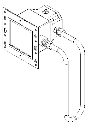
4 Mechanical Assembly
This section details the basic mechanical assembly information and important dimensions necessary for installation.
4.1 Short Range Reflector Panel Heater
The short range Reflector Panel Heater is suitable for use from 0.5m to 2.5m.

4.2 Long Range Reflector Panel Heater
The Long Range Reflector Panel Heater is suitable for use from 2.5m to 5m

5 Installation
The Reflector Panel Heaters are designed to allow installation to be performed by a single operator. The installation procedure is split into mechanical installation and electrical installation.
5.1 Mechanical Installation
Follow these instructions carefully. Do not attempt to dismantle the Reflector Panel Heater in any way.
5.1.1 Replacement of standard retro-reflector panels
If the Reflector Panel Heater is replacing a standard retro-reflector panel then the existing duct cut out and mounting holes can be re used.
- Ensure the system is switched off.
- Loosen the 4 screws that clamp the retro-reflector assembly in position.
- Lift the assembly up and outwards to release it from behind the screw heads.
- Slot the Reflector Panel Heater assembly over the 4 screw heads and allow its weight to be supported on the exposed sections of the thread.
- Tighten the 4 screws to clamp the Reflector Panel Heater assembly in position.
5.1.2 Installation of Reflector Panel Heaters
If installing the Reflector Panel Heater to a new duct location follow the procedure below:
- Stick the retro-reflector cut-out template to the outside of the duct wall opposite the transmitter/receiver, ensuring that point X* is directly opposite point X on the other template. (This will ensure that the transmitter’s IR beam hits the centre of the retro-reflector).
- Drill 6 mounting holes (7mm diameter) in the positions marked J on the template.
- Following outline K, cut a square aperture in the duct wall.
- Insert the two retro-reflector panel support bars through the aperture and attach them to the inside of the duct using M6 washers and nuts. Ensure that the threaded holes in the support bars line up with the holes drilled in the duct.
- Fit four M6 x 16 cap head screws into the holes in the support strips but do not tighten. Leave approximately 5mm of thread exposed on the outside of the duct.
- Slot the retro-reflector assembly over the heads of the screws and allow its weight to be supported on the exposed sections of thread. Tighten the four screws to clamp the retro-reflector assembly in position.
5.2 Electrical Installation
- Isolate all associated power supplies and ensure that they remain OFF during this procedure.
- Fit an approved cable gland to the junction box cable entry to be used for the power connections to the Reflector Heater Panel, using sealing washers where necessary to maintain ingress protection rating.
- Fit approved blanking plugs to all unused cable entries. 4. Make appropriate electrical connections as shown in the following section.
5.2.1 Terminal Connection Diagram- Short Range Reflector Panel Heater
The short range Reflector Panel Heater is a resistive heater requiring an 18-28Vdc (nominal 24Vdc) supply. All connections are made inside the junction box supplied as part of the Reflector Panel Heater Assembly. To allow for a wide range of supply voltage, two power terminals (2 and 3) are available
| Terminal Identification | Wire Colour | Customer Connection |
| 1 | White | 0V |
| 2 | Black or Brown | >20Vdc |
| 3 | Blue | 18-20Vdc |
| 6 | Green | Earth |
Note: If the voltage drops below 20Vdc in operation, the 24Vdc input should be connected to terminal 3 instead of terminal 2.
Terminal 2 connects to a 100Ω heater; terminal 3 connects to a 68Ω heater.
If the Cross Duct Excel shares a power supply cable with the Reflector Panel Heater, a check must be made to verify that a minimum voltage of 18V is available at the Cross Duct Excel when the Reflector Panel Heater is operating

6.2.2 Terminal Connection Diagram- Long Range Reflector Panel Heater
The long range Reflector Panel Heater is a resistive heater requiring an 18-28Vdc (nominal 24Vdc) supply. All connections are made inside the junction box supplied as part of the Reflector Panel Heater Assembly. To allow for a wide range of supply voltage, two power terminals (2 and 3) are available.
| Terminal Identification | Wire Colour | Customer Connection |
| 1 | White | 0V |
| 2 | Black or Brown | >20Vdc |
| 3 | Blue | 18-20Vdc |
| 6 | Green | Earth |
Note: If the voltage drops below 20Vdc in operation, the 24Vdc input should be connected to terminal 3 instead of terminal 2.
Terminal 2 connects to a 33Ω heater; terminal 3 connects to a 23Ω heater.
If the Cross Duct Excel shares a power supply cable with the Reflector Panel Heater, a check must be made to verify that a minimum voltage of 18V is available at the Cross Duct Excel when

Our Product Range
Fixed Gas Monitoring

Honeywell Analytics offers a wide range of fixed gas detection solutions for a
diverse array of industries and applications including: Commercial properties, industrial applications, semiconductor manufacturers, energy plants and petrochemical sites.
- Detection of flammable, oxygen and toxic gases (including exotics)
- Innovative use of 4 core sensing technologies – paper tape, electrochemical cell, catalytic bead and infrared
- Capability to detect down to Parts Per Billion (ppb) or Percent by Volume (%v/v)
- Cost effective regulatory compliance solutions
Portable Gas Monitoring

When it comes to personal protection from gas hazards, Honeywell Analytics has a wide range of reliable solutions ideally suited for use in confined or enclosed spaces.
These include:
- Detection of flammable, oxygen and toxic gases
- Single gas personal monitors – worn by the individual
- Multi-gas portable gas monitors – used for confined space entry and regulatory compliance
- Multi-gas transportable monitors – used for temporary protection of area during site construction and maintenance activities
Technical Services

At Honeywell Analytics, we believe in the value of great service and customer care. Our key commitment is providing complete and total customer satisfaction. Here are just a few of the services we can offer:
- Full technical support
- Expert team on hand to answer questions and queries
- Fully equipped workshops to ensure quick turnaround on repairs
- Comprehensive service engineer network
- Training on product use and maintenance
- Mobile calibration service
- Customised programmes of preventative/corrective maintenance
- Extended warranties on products