Bosch PTM21 Bluetooth Module User Manual


BOSCH PTM21 Bluetooth Module

| Document Version | Compo-nent Version | Date | Author | Description | Status |
| 1.0 | 1.0 | 05.07.2020 | Bosch PT | Released |
About this Document
Purpose and Audience
This Product Specification provides details on the functional, operational, and electrical characteristics of the Bosch PTM21 module. It is intended for hardware design, application, and purpose team engineers. The product is referred to as “the PTM21” or “the module” within this document.
Overview
The PTM21 is a small form factor connectivity module based on Bluetooth Low Energy 4.2 (BLE) technology. This is the 1st generation of the connectivity module of this type.
The basic concept of PTM21 is that it works as a gateway between a BLE client; mobile phone or a power tool with integrated PTM21 and tool electronics. The PTM21 uses Bluetooth Low Energy 4.2 technology for wireless data communication and it uses Smart Tools Protocol (STP) (Bosch Power Tools proprietary communication protocol) bus to communicate with the main electronics. The module’s design is based on TI-CC2640R2 microcontroller.
Block Diagram

Communication interface
Hardware layer -> UART
- Half Duplex – One wire interface. HW adoption on the host board necessary.
- Baud rate: 115200 bps
- Data format: 8N1
Communication layer -> STB (Smart Tools Bus)
Position of the PTM21 on the host board

Guidelines for Enclosure and Ground Plane
- There should not be any ground directly below the antenna
Ensure that there is no component, mounting screw, or ground plane near the tip of the antenna or the length of antenna. No large components should be placed near the antenna. - No battery cable, microphone cable, or any trace should cross the antenna trace on the PCB on the same side of the antenna.
- The antenna should not be covered by a metallic enclosure completely. If the product has a metallic casing or a shield, the casing should not cover the antenna. No metal is allowed in the antenna near field.
- Ensure the paint on the plastic enclosure is non-metallic near the antenna for best performance.
- The orientation of the antenna should be in line with the final product orientation so that the radiation is maximized in the desired direction. The polarization of the receive antenna and the position of the receive antenna should be taken into account to orient the module in a way that maximum radiation occurs.
- Keep away from antenna, as far as possible, large metal objects to avoid electromagnetic field blocking
- Keep any components that may radiate noise or signals within the 2.4GHz – 2.5GHz frequency-cy band far away from the antenna or better yet, shield the components that are generating the noise. Any noise radiated from the customer PCB in this frequency band will degrade the sensitivity of the module
Mechanical Details
Dimensions


| No. | Item | Dimension | Tolerance |
| 1 | Width | 15 mm | ±0.2 |
| 2 | Length | 25.4 mm | ±0.2 |
| 3 | Height | 2.1 mm | ±0.2 |
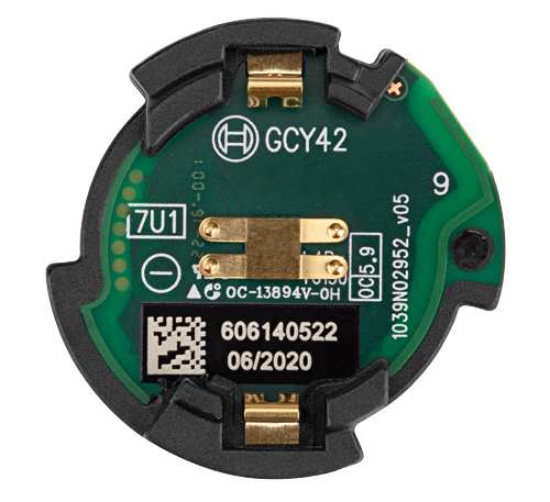
Label

Specifications
Recommended operating conditions
| Symbol | Parameter | Condition | Min | Typ. | Max | Unit |
| Ta | Ambient temperature | -20 | +50 | °C | ||
| Vdd | 3V3 Power supply | 2.8 | 3 | 3.3 | V |
Current consumption
| Parameter | Condition | Min | Typ. | Max | Unit |
| Operating current | Connected | 1,4 | 1,5 | 1,8 | mA |
| Operating current | Connected and communicating | 2 | 2,2 | 2,4 | mA |
| Sleep mode | Plus advertising | 4 | 5 | 6 | uA |
Bluetooth
| Parameter | Condition | Min | Typ. | Max | Unit |
| Frequency | 2402 | 2480 | MHz | ||
| Output power | 0 | dBm | |||
| Sensitivity | -90 | dBm |
Cautions
Design notes
- Follow the conditions written in this specification, especially the control signals of this module.
- The supply voltage should abide by the maximum ratings
- The supply voltage must be free of AC ripple voltage (for example from a battery or a low noise regulator output). For noisy supply voltages, provide a decoupling circuit (for example a ferrite in series connection and a bypass capacitor to ground of at least 47 μF directly at the module).
- This module should not be mechanically stressed when installed.
- Keep this module away from heat. Heat is the major cause of decreasing the life time of these modules.
- Keep this module away from other high frequency circuits.
- Refer to the recommended pattern when designing a board.