LG ETWCERBS01 RF Module User Manual
LG ETWCERBS01 RF Module User Manual


Features
ETWCERBS01 is the small size and low power module for IEEE 802.11ac wireless LAN & BT5.0 + HS. ETWCERBS01 is based on Realtek RTL8822CU solution.
- IEEE 802.11 a/b/g/n/ac 2T2R Dual Band MIMO
- Bluetooth: 5.0+ HS , BLE
- Size: 18.4 x 27.0 x 2.9mm
- Two stream spatial multiplexing up to 300Mbps(802.11n) / 867Mbps(802.11ac)
- Use on-chip OTP (One-Time Programmable)
- Host Interface: USB2.0 (WLAN & BT)
- This model is using the common USB2.0 to control WLAN and BT
- Security: WAPI, WPA, WPA2
- QoS support of WMM
Picture of Product


Installation Manual
Install the module like below in the back of the TV.

Block Diagram

Absolute Maximum Ratings
Caution: The specifications in Table 1 define levels at which permanent damage to the device can occur. Function operation is not guaranteed under these conditions.
Operating at absolute maximum conditions for extend periods can adversely affect the long-term reliability of the device.
Parameter |
Min | Max | Unit |
| Storage Temperature | -10 | +80 | ℃ |
Storage Humidity (40℃) |
– | 90 | % |
< Table 1 >
Other conditions
- Do not use or store modules in the corrosive atmosphere, especially where chloride gas, sulfide gas, acid, alkali, salt or the like are contained.
Also, avoid exposure to moisture. - Store the modules where the temperature and relative humidity do not exceed 5 to 40℃ and 20 to 60%.
- Assemble the modules within 6 months. Check the soldering ability in case of 6 months over.
Operating Conditions
Parameter |
Min | Typ | Max | Unit |
| Ambient Temperature | 0 | – | 70 | ℃ |
Ambient Humidity (40℃) |
– | – | 85 | % |
| Supply Voltage | 3.135 | 3.3 | 3.6 | Vdc |
Standard Test Conditions
The Test for electrical specification shall be performed under the following condition Otherwise this following conditions, not guaranteed this performance.
Ambient condition
Temperature |
25 ± 5℃ |
| Humidity | 65 ± 5% |
Power supply voltages
Input power |
Supply Voltage |
| VDD_3.3V | 3.135 ~ 3.6V |
Pin Description
| Pin | SYMBOL | I/O | DESCRIPTION |
| 1 | NC | – | Not Connect |
| 2 | NC | – | Not Connect |
| 3 | NC | – | Not Connect |
| 4 | NC | – | Not Connect |
| 5 | GND | – | GND |
| 6 | WL_USB_DP | I/O | USB D+ |
| 7 | WL_USB_DN | I/O | USB D- |
| 8 | GND | – | GND |
| 9 | NC | Not Connect | |
| 10 | NC | Not Connect | |
| 11 | GND | GND | |
| 12 | NC | Not Connect | |
| 13 | GND | GND | |
| 14 | BT_WAKE _HOST | BT CHIP WAKES UP HOST | |
| 15 | HOST _WAKE_BT | HOST WAKES UP BT CHIP | |
| 16 | NC | Not Connect | |
| 17 | NC | – | Not Connect |
| 18 | GND | – | GND |
| 19 | NC | – | Not Connect |
| 20 | GND | – | GND |
| 21 | GND | – | GND |
| 22 | NC | – | Not Connect |
| 23 | GND | – | GND |
| 24 | GND | – | GND |
| 25 | GND | – | GND |
| 26 | WLAN_WA KE_HOST | O | WLAN CHIP WAKES UP HOST |
| 27 | NC | – | Not Connect |
| 28 | CHIP_EN | I | Shutdown CHIP |
| 29 | GND | – | GND |
| 30 | VDD33 | I | 3.3V |
| 31 | GPIO5 | I/O | General Purpose Input/Output Pin |
| 32 | GND | – | GND |
| 18 | GND | – | GND |
| 19 | NC | – | Not Connect |
Note 1. Pin 14 (BT_WAKE_HOST) is pulled up to 3.3V, the port should be configured to be active low
Note 2. Pin 15 (HOST_WAKE_BT) is no pull-up or pull-down inside the module
Note 3. Pin 26 (WLAN_WAKE_HOST) is pulled up to 3.3V, the port should be configured to be active low
Note 4. Pin 28 (CHIP_EN) is pulled up to 3.3V, do not pull up on Host
Outline Drawing

Packing Information


Certification
- Brand : LG Innotek
- Manufacturer Address : E1/E3, 30, Magokjungang 10-ro, Gangseo-gu, Seoul, 07796, Korea
- Product Name : WiFi
- Factory : PT. LG INNOTEK INDONESIA
- Factory Address : Bekasi International Industrial Estate, Blok C8 NO. 12 & 12 A, Desa Cibatu, Cikarang Selatan, Bekasi 17750 – Indonesia
* Connection and use of this communications equipment is permitted by the Nigerian Communications Commission
Regulatory Statement (FCC)
Part 15.19 Statement
This device complies with Part 15 of the FCC Rules. Operation is subject to the following two conditions:
- this device may not cause harmful interference, and
- this device must accept any interference received, including interference that may cause undesired operation.
Part 15.105 Statement (Class B)
This equipment has been tested and found to comply with the limits for a Class B digi tal device, pursuant to part 15 of the FCC Rules.
These limits are designed to provide reasonable protection against harmful interference in a residential installation. This equipment generates, uses and can radiate radio frequency energy and, if not installed and used in accordance with the instructions, may cause harmful interference to radio communications. However, there is no guarantee t hat interference will not occur in a particular installation. If this equipment does cause harmful interference to radio or television reception, which can be determined by turning the equipment off and on, the user is encouraged to try to correct the interference by one or more of the following measures:
- Reorient or relocate the receiving antenna.
- Increase the separation between the equipment and receiver.
- Connect the equipment into an outlet on a circuit different from that to which the receiver is connected.
- Consult the dealer or an experienced radio/TV technician for help.
Part 15.21 Statement
Any changes or modifications not expressly approved by the party responsible for compliance could void the user’s authority to operate this equipment. This device must not be co-located or operating in conjunction with any other antenna or transmitter.
Responsible Party Information (Supplier’s Declaration of Conformity)
LG Innotek USA Inc.
Street Address: 2540 N 1st ST STE 400 SAN JOSE, CA 95131-1016
PHONE: +1-408-350-7661 /
FAX: +1-408-955-0329
Regulatory Statement (FCC)
Regulatory notice to host manufacturer according to KDB 996369 D03 OEM Manual v01
List of applicable FCC rules
This module has been granted modular approval as below listed FCC rule parts.
- FCC Rule parts 15C (15.247)
Summarize the specific operational use conditions
The OEM integrator should use equivalent antennas which is the same type and equal or less gain then an antenna listed in this instruction manual.
RF exposure considerations
The module has been certified for integration into products only by OEM integrators under the following condition:
- The antenna(s) must be installed such that a minimum separation distance of at least 2
0 cm is maintained between the radiator (antenna) and all persons at all times. - The transmitter module must not be co-located or operating in conjunction with any other antenna or transmitter except in accordance with FCC multi-transmitter product procedures.
- Mobile use
As long as the three conditions above are met, further transmitter testing will not be required. OEM integrator should provide the minimum separation distance to end users in their end-product manuals.
Frequency |
Antenna type & Peak gain |
| 2402 ~ 2480 MHz (BT) | HQ Antenna type: Diplole antenna (Peak Gain : 2.93 dBi) IP Antenna type: Diplole antenna (Peak Gain : 2 dB) |
| 2412 ~ 2472 MHz (WLAN 2.4 GHz) | 01 Antenna type: Planar Inverted F antenna (Peak Gain : 3.35 dBi) A7 Antenna type: Diplole antenna (Peak Gain: 2 dBi) |
| 5180 ~ 5825 MHz (WLAN 5 GHz) | 01 Antenna type: Planar Inverted F antenna
A7 Antenna type: Diplole antenna (Peak Gain: 2 dBi)
|
Any new antenna type, higher gain than listed antenna should be met the requirements of FCC rule 15.203 and 2.1043 as permissive change procedure.
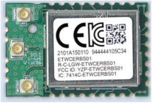
Label and compliance information
End Product Labeling
The module is labeled with its own FCC ID and IC Certification Number. If the FCC ID and IC Certification Number are not visible when the module is installed inside another device, then the outside of the device into which the module is installed must also display a label referring to the enclosed module. In that case, the final end product must be labele d in a visible area with the following:
- Contains FCC ID: YZP-ETWCERBS01
- Contains IC: 7414C- ETWCERBS01
Information on test modes and additional testing requirements
OEM integrator is still responsible for testing their end-product for any additional compliance requirements required with this module installed (for example, digital device emissions, PC peripheral requirements, additional transmitter in the host, etc.).
Additional testing, Part 15 Subpart B disclaimer
The final host product also requires Part 15 subpart B compliance testing with the modular transmitter installed to be properly authorized for operation as a Part 15 digital device. OEM integrator must install this transmitter module inside the enclosure of host device not to be user accessible to compliance with antenna requirements in FCC Rule Section.
Regulatory Statement (ISED)
RSS-GEN, Sec. 7.1.3–(licence-exempt radio apparatus)
This device complies with Industry Canada licence-exempt RSS standard(s). Operation is subject to the following two conditions:
- this device may not cause interference, and
- this device must accept any interference, including interference that may cause unde sired operation of the device.
Antennas list
This module is certified with the following external antenna.
Frequency |
Antenna type & Peak gain |
| 2402 ~ 2480 MHz (BT) | HQ Antenna type: Diplole antenna (Peak Gain 2.93 dBi) IP Antenna type: Diplole antenna (Peak Gain : 2 dB) |
| 2412 ~ 2472 MHz (WLAN 2.4 GHz) | 01 Antenna type: Planar Inverted F antenna (Peak Gain : 3.35 dBi) A7 Antenna type: Diplole antenna (Peak Gain: 2 dBi) |
| 5180 ~ 5825 MHz (WLAN 5 GHz) | 01 Antenna type: Planar Inverted F antenna
A7 Antenna type: Diplole antenna (Peak Gain: 2 dBi)
|
Regulatory Statement (CE)
Simplified EU Declaration of Conformity
“Hereby, LG Innotek Co., Ltd. declares that the radio equipment type RF Module is in compliance with Directive 2014/53/EU. The full text of the EU declaration of conformity is available at the following internet address: http://www.lginnotek.com/en/compliance-information.
The antenna(s) must be installed such that a minimum separation distance of at least 20 cm is maintained between the radiator (antenna) and all persons at all times.
This device must not be collocated or operating in conjunction with any other antenna or transmitter. The host manufacturer integrating this module should be assessed total compliance with all essential requirements regarding this radio module.
The use of the 5150 –5350 MHz band is restricted to indoor use only. This restriction will be applied in all member states.
The host manufacturer has the responsibility that the host device should be compliance with all essential requirement of RED.
The product is compliant with the RED Article 10(2) because the product is operated at least one Member State without infringing applicable requirements on the use of radio spectrum.
Manufacturer Name: LG Innotek Co., Ltd.
Manufacturer Address: 26, Hanamsandan 5beon-ro, Gwangsan-gu, Gwangju, 506-731, Korea
LG Innotek Co., Ltd, Europe Branch
Am Limespark 2 (Innovapark) 65843 Sulzbach am Taunus, Germany
Tel.49-(0)6196-64038-70 /
Output power Tune-up value (CE)
Item |
Frequency | Target. Power (EIRP, Sum) | Tolerance | |
| Standard | IEEE 802.11 a/b/g/n/ac | |||
Frequency |
2.4 G | 2 412 – 2 472 MHz | 16.5 dBm | |
5G Low |
5 150 – 5 250 MHz |
19.5 dBm | ||
5 250 – 5 350 MHz |
16.9 dBm | ±3dBm | ||
| 5G High | 5 725 – 5 850 MHz | 10.6 dBm | ||
| Item | Frequency | Target. Power (EIRP) |
| BT | 2 402 – 2 480 MHz | 6.5 dBm |
| BT LE | 2 402 – 2 480 MHz | 4.5 dBm |